Continue to Site

Eng-Tips is the largest engineering community on the Internet

Intelligent Work Forums for Engineering Professionals

  • Congratulations KootK on being selected by the Eng-Tips community for having the most helpful posts in the forums last week. Way to Go!

Allowable Stress Formula / Equation # 1

Status
Not open for further replies.

greencircle

Mechanical
Nov 19, 2014
88
Guys,

Sorry to ask these questions. With your help I am trying to understand the code & learn the calc procedure.

On one reference calcs i have it says:

ALLOWABLE UNIT STRESSES - 6063-T6 Aluminum Alloy
Allowable Bending Stress: Within 1" of weld
Fa = 18000 x 1.33 x 0.85 = 20349 PSI
Allowable Bending Stress: Greater than 1" from weld
Fa =18000 x 1.33 =23940 PSI

Questions :
1. On the underlined formula, I believe that 0.85 is got to do something about the 85% of the allowable stress. Not sure what the 1.33 is? I couldn't find which of the equation#/formula was used to develop 18000 x 1.33 x 0.85.
2. I believe in the table 6-1 & 6-2 of LTS-6 there is 3 different stresses on the table. Tension, Compression, Shear & bearing. Which of these 4 should be used for Bending?
3. On 6-1 & 6-2 I did not see 18ksi(18000 psi) any where for 6063 alloy. Any idea how this might have obtained?

Thanks
GC

 
Replies continue below

Recommended for you

Aashto - Standard Specifications for Structural Supports for Highway Signs, Luminaires, and Traffic Signals, 2009
Link
Link

Even in 2013 (LTS-6) also these tables remain same.
 
The 1.33 is for an 33% increase in the allowable stress due to the load combination. Certain load combinations will have this increase. I don't have the code in front of me (I'm out of the office for a while) but I assume the 0.85 is to compare the analysis of the load combination to the allowable stress for simplicity.

The allowable bending stress is your 18ksi or whatever you adjust it by. It's not the other four.

The 18ksi would be 0.6*Fy so roughly 0.6*31=18.6ksi. Hope this helps.
 
Thank you BridgeEI.

Its now clear why we multiply by 1.33. I recognized this on the table 3.4.1 - Group load combination.
GL2 & GL3 require 133%. Thanks for directing me.

BridgeEI said:
The 18ksi would be 0.6*Fy so roughly 0.6*31=18.6ksi. Hope this helps.

Based on this, Fa = (0.6 Fy) x 1.33 x 0.85
Am I right?

I wish there was a equation reference number. (I would like documenting it while calculating for debugging)

I am putting one together. But, just checking, if any of you have a spread sheet available.
 
It depends on which load combination you're checking. Your allowable stress will always be 0.6Fy. Then depending what you're looking at you may be allowed to increase the allowable stress.

Like I said I'm doing this from memory, but I don't believe you need the 0.85. I think that's more of a book keeping issue. For instance if you have a calc set up that always allows for the 33% increase you don't need the 0.85 but if you have an load case where the increase isn't allowed then you need to use the 0.85 to offset the increase.

I think the 0.85 corresponds to an increase of 15% and 0.75 is for a 33% increase.
 
BridgeEI - I want to check for GL3 loading combination. Also, thank you very much for explaining about how to use the allowable stress (0.6F[sub]y[/sub])

After a bit more reading, here is what I understood so far.

I believe that 0.85 is got to do with 85% of allowable stress. This is applicable to only 1" from the welded connection though.

There are 4 types of stress to calculate & check.

[ol 1]
[li]Allowable Bending stress within 1" of weld. F[sub]B[/sub][/li]
[li]Allowable Axial Compressive stress within 1" of weld. F[sub]A[/sub][/li]
[li]Allowable Shear stress within 1" of weld. F[sub]v[/sub][/li]
[li]Allowable Shear stress greater than 1" from weld. F[sub]v[/sub][/li]
[/ol]

0.85 (85%) reduction of allowable stress is applicable to only the 1-3. The last one will used the allowable stress as-is.

One thing I didn't follow is that the Shear stress is tied to "h/t <= 39 ratio". Not sure how to do this. Is this height of the total pole/ thickness of the pole. This doesn't make sense. if the pole is 10 ft tall with 0.25in wall. Thats will be

120in/0.25in = 480

I am sure that I am not doing this right. Any reference / example to read about this.

Thanks
GC
 
The h/t should be the diameter and wall thickness of the pole. It follows AISC nomenclature but isn't quite intuitive for when you first see it.
 
Thank you for helping me understand h/t. I tried applying this to a old calculation on file. Here is what I came up with.
When you have a moment, can you see if I am doing this right, please.

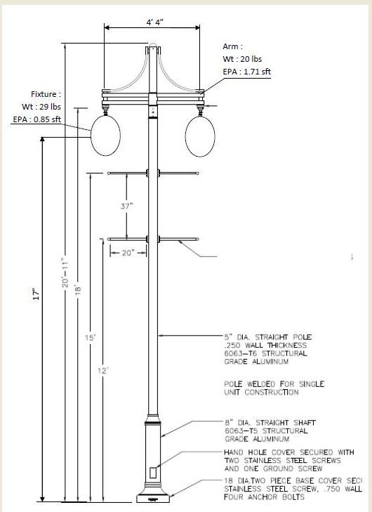
At this point, I am concerned only about h/t. There are 2 segments of pole :

[ul]
[li]Dia 8 x 0.25" wall x 4ft---------------shouldn't h/t be 8/0.25 = 32 [/li]
[li]Dia 5 x 0.25"wall x 14ft---------------shouldn't h/t be 5/0.25 = 20 [/li]
[/ul]

Near_Weld_zd4bik.jpg

Away_From_Weld_maqob4.jpg


Pole drawing :
pole_a89hjy.jpg


Thanks,
GC
 
Status
Not open for further replies.

Part and Inventory Search

Sponsor