Eng-Tips is the largest engineering community on the Internet

Intelligent Work Forums for Engineering Professionals

  • Congratulations waross on being selected by the Tek-Tips community for having the most helpful posts in the forums last week. Way to Go!

Alternatives for Symmetry and Concentricity

Status
Not open for further replies.

JBecks

Mechanical
May 8, 2023
6
0
0
US
I am working with some legacy prints that make use of symmetry and concentricity. Looking for advice on alternative tolerance options that can replace these. I am fairly green to certain areas of GD&T and would appreciate some input.

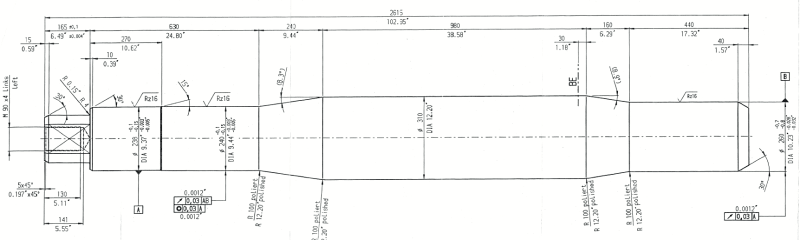
Parts are mainly rotating steel shafts. Print below.

Print_snip_w5uqtn.png


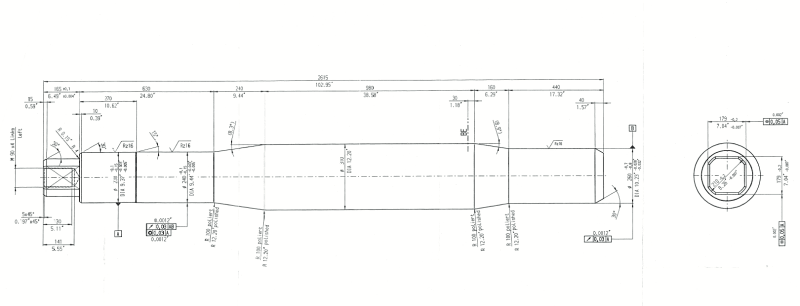
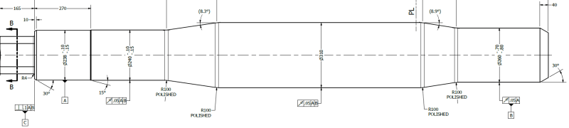
Correct me if I am wrong, but I believe the circular runout shown will control the concentricity to a degree. I am thinking of changing this to total runout (seems more appropriate here to control the whole surface) and removing the concentricity control altogether?

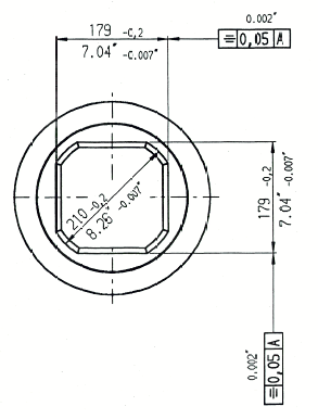
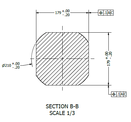
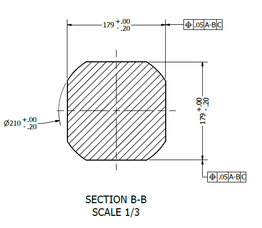
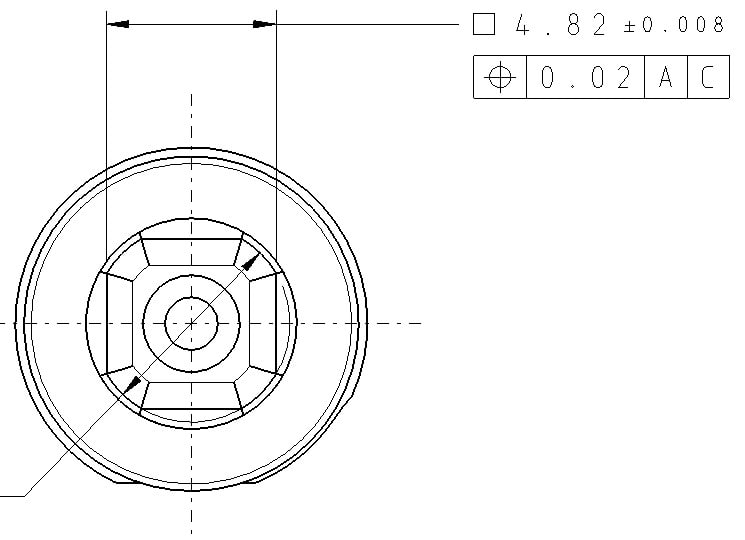
I get the idea of the symmetry to keep that 'socket' end centered on the A datum axis. What would be the best way to accomplish this?
 
Replies continue below

Recommended for you

ASME or ISO GPS?
If ASME you can use position or runout (circular or total)
If ISO GPS, you can keep concentricity and/or symmetry or you also can replace them with position (you might want also to use ACS, but I am not so sure about that)
The print is blurry. Could you, please, post another version with better quality.

 
For rotating shafts, circular runout will take care of balance. You don't need total runout unless you want to limit the taper or waviness of the form along the shaft more than the size tolerance and rule #1 do it.
Symmetry of a toleranced width can be replaced by position.
 
JBecks,

In discussions on symmetry in this Forum, I have always asked why I would ever use symmetry. Specifications like concentricity and symmetry allow me to apply sloppy dimension tolerances to features, but locate them accurately about an axis. Why would I do this?

Position works. Run-out works. If your part must be dynamically balanced, specify the rpms and the force or displacement that the part shall be tested to.

--
JHG
 
Burunduk said:
For rotating shafts, circular runout will take care of balance. You don't need total runout unless you want to limit the taper or waviness of the form along the shaft more than the size tolerance and rule #1 do it.

Understood on this, thanks.

Burunduk said:
Symmetry of a toleranced width can be replaced by position.

How would that look to achieve the same results as symmetry? This is where I am struggling.

greenimi said:
ASME or ISO GPS?

ASME.

greenimi said:
The print is blurry. Could you, please, post another version with better quality.

Lets see if this is better.

Print_snip1_mf0kbn.png


Print_snip_2_hxfd6t.png
 
OP said:
How would that look to achieve the same results as symmetry?

You don't!

Because of the crappy - of extremely poor quality- definition of the symmetry in ASME (no wonder has been removed from the ASME Y14.5-2018 standard) you hardly want the symmetry as being your design intent.
Otherwise stated, not many (if any) real world designs are fitting the symmetry definition.


Thank you greenimi, Burunduk, drawoh for the responses.

Figured it would be easier for me to draw the changes and provide them for critique of my understanding of how to effectively replace these.

I used runout and removed the concentricity, and have attempted replacement of the symmetry with position using a new C datum.

Print_snip3_bs2epr.png


Print_snip4_jp7oku.png
 
JBecks,

The drafting style suggests that the original drawing is from Europe. It probably used ISO dimensioning and tolerancing standards and not ASME Y14.5.

By the way, is there a reason that the tolerance values were doubled? If you were aiming at keeping the requirements roughly the same, the Position tolerance values should be equal to the Symmetry tolerance values.

Evan Janeshewski

Axymetrix Quality Engineering Inc.
 
JBecks,

I don't think that what is shown on yoru drawing (regardless if ISO or ASME) is depicting the trully design intent.

I would use datum feature A defined to A-B; the same for B (wrt to A-B)
Then the left face/ feature C to be perpendicular to A-B

Consequently, the square to be positioned to A-B primary and C secondary.

 
axym said:
By the way, is there a reason that the tolerance values were doubled?

No, there isn't right now. I will adjust several tolerances later due to wear on existing mating components, etc. Still getting field dimensions on those so a few tolerance values are placeholders for now.

As for ISO, originally that is likely - I work with a lot of drawings that are German, US, sometimes a nice blend of both to really confuse me.

I will spend more time researching the nuisances between to 2 to avoid overlapping specs since I jump back and forth so often. Any resources (website, etc) you would recommend?

greenimi said:
I would use datum feature A defined to A-B; the same for B (wrt to A-B)
Then the left face/ feature C to be perpendicular to A-B

Consequently, the square to be positioned to A-B primary and C secondary.

Not sure I understand. What design intent do you think is not being depicted?

Left face/feature C I have perpendicular to A & B already - are you saying this is done incorrectly?

Square position is drawn defined by A & C, you are recommending to use B as well? If so, why? Wouldn't datum A axis and datum B axis effectively have the same control on the feature? Might be misunderstanding this
 
Yes, I would say that based on your original drawing (and the fact the journal bearings are shown as datum features), A-B primary and C secondary is reflecting the design intent.
Therefore, |A-B|C| should be your Datum Reference Frame and consequently your coordinate system.

 
Thanks greenimi.

I have not come across that notation before. Usually always see |A|B|C| vs |A-B|C|. I understand you are saying the difference is defining A & B datums as both primary in the latter. Is this commonly used?

Here is the updated Section B-B that should capture what you are advising.

Print_snip5_yfub1a.png


I believe your other advice was a similar change to the runout? Making |A-B| primary instead of |A|B| due to nature of bearings? I understand this idea as well, but I am curious how this plays out in machining and the potential impact on runout vs using primary-secondary. Is this more of a clerical importance vs. a potential difference in final machined part?
 
Burunduk said:
What useful constraint does C secondary in [A-B,C] add for the tolerance of position?
Datum feature C was indicated by the OP on his drawing and I am thinking if is a trust surface then it is needed.
Might be helpful in imposing/forcing simultaneous requirements with other features (not currently defined on OP's drawing) and I think might also help in stabilizing the part during inspection.
Not all the feature might benefit from it (as secondary)--like circular runout ---
But, again, some features might find it helpful.
 
Side question, but got me wondered.
Can we use the Square symbol if the FoS have rounded/chamfered edges?
square_l7ntca.jpg


Btw the OP picture is 1st angle. ASME is 3rd angle. Also that's a very german style drawing
 
Wuzhee said:
Can we use the Square symbol if the FoS have rounded/chamfered edges?

With or without the chamfers, the square feature (when considered as a single feature and not two width-type features of size) is an irregular feature of size.
As such, it is better to control it by position at MMC, similarly to the idea shown in figure 7-29 of Y14.5-2018. This allows the use of the boundary concept. Otherwise, with RFS, it is not clear what the shape of the tolerance zone is, what resolved geometry should fit in it, and how should it be obtained from the actual feature.
 
Status
Not open for further replies.
Back
Top