Continue to Site

Eng-Tips is the largest engineering community on the Internet

Intelligent Work Forums for Engineering Professionals

  • Congratulations KootK on being selected by the Eng-Tips community for having the most helpful posts in the forums last week. Way to Go!

Amada software etching 1

Status
Not open for further replies.

mikeybob125

Automotive
Nov 24, 2014
15
I have Ben trying to etch part numbers on my parts with a fo4020 co2 laser. I can not get sheetworks to take anything but full cuts unless I change the E-code in dr.abe after the nesting. The guy I took over for was able to do it and it shows up as a red line text in the data manager and I think he was using DXF files. My train time with him was short. Any help would be grate.
 
Replies continue below

Recommended for you

If you're using Dr. Abe as nesting software you can the assigned E code in the part edut side. Highlight the part and click the part edit function. Click on Manual Assign/Edit. Find the area you want to etch and change the drop down to E010. Take the lead in length to 0 and turn off the Laser Pierce in the Pierce Type drop down.
 
If that doesn't work, Open it up using AP100. The etched lines are usually refered to bend lines.
You can then make them etch using this method, instead of cutting.
 
Easiest way would be making a Layer name as Etch layer. Then its quite easy to manage from there in DR.ABE.
I use a certain laser as etch layer and that works fine for me
 
Thanks for the ideas. I know how to change the E-code in Dr.abe but it is very time consuming with multiple parts or same parts on different sheets. But the idea of using ap100 and saving it to data manager. But I have heard of the layer method and don't have a clue where to start.
 
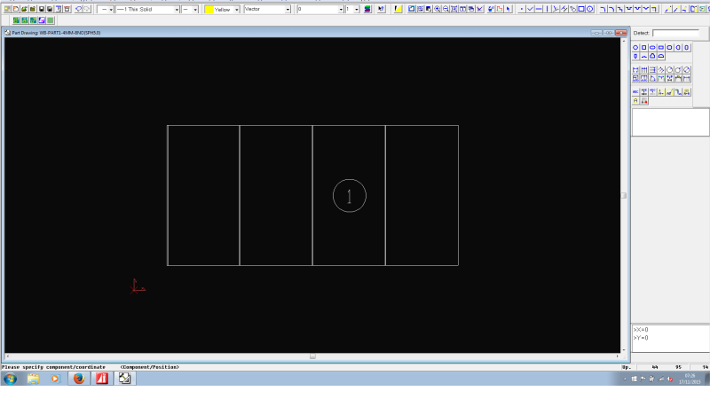
Import your part:
1_gnrkey.png


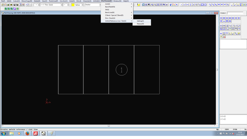
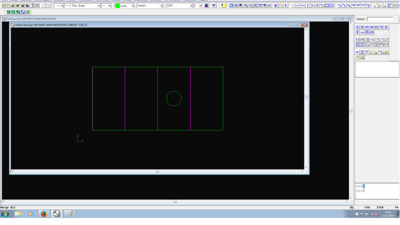
Go to Pre-Process> unfold reference line> setting
2_sozxah.png


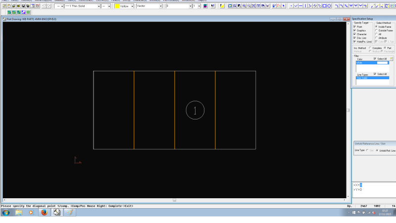
Select/drag the lines you want to etch. Right click after and press complete
3_blkv1p.png


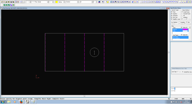
This should make the lines pink.

4_hmit2o.png


After that, click unfold/merge all button:
5_kg2tcj.png

Then save your part in the SDD. Open it in Dr.Abe, Those pink lines will now etch.
 
yes it helped using ap100. now I am trying to figure gout the layer method on sheet works. have not gotten very far yet. but thanks again
 
I use an older version of Autocad and just open the dxf file for it. Create a layer named etch and go to town. I used to leave encouraging messages etched to welders since they all get powder coated anyways lol. But you can usually get a light version of autocad 2000 for free online if ya look around. Thats all i have.
 
Creating a layer in autocad as etching doesn't work when making your drawing a part using this Amada software. When importing a part, unless changed, you have to specify what lines are cut and etched.
The example i posted above shows the etched lines made pink before confirming the 'outline' of the rest of the part to cut.

Unless anyone can show me a quicker and easier method? :)
 
If you use the autocad 2d model for your cutting. Creating a specific layer will solve this. For example:
First go to Preference in DR.ABE BLANK
goto Toolassignment
goto Path Assignment Method
Then Mark the box for Etch Layer and write the prefered name. For example Etchning

When in 2d autocad
Create New Layer - Etchning
And draw the desired lines or import and change into that layer.

Questions?
 
Just an update. The operator that ran the laser before me stopped by and showed me a fast easy way with sheet works, you define the part then add a text it will only work with areal-narrow font then close change the body name to ETCH and continue. Now in settings you have to change the etch setting from sketch to ETCH and done! If you need more details let me know I'm alway willing to help those who help me and thanks again
 
Status
Not open for further replies.

Part and Inventory Search

Sponsor