Eng-Tips is the largest engineering community on the Internet

Intelligent Work Forums for Engineering Professionals

  • Congratulations waross on being selected by the Tek-Tips community for having the most helpful posts in the forums last week. Way to Go!

Amp rating of current meters 2

Status
Not open for further replies.

Mbrooke

Electrical
Nov 12, 2012
2,546
0
0
US
Do analog amp meters have a current limitation?

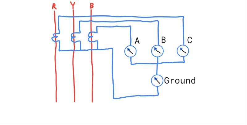
Basically I want to monitor leakage current on a 3 wire system. A, B, C meters 0-2000 amps, Ground meter 0-30 amps, possibly 0-5 amps range.

Question is, what if I get a persistent ground fault over 30 amps? Will my meter burn up? How will the burden of each meter effect the others under normal and GF conditions?


autodraw_8_12_2020_qvh6o9.jpg
 
Replies continue below

Recommended for you

Dear Mr. davidbeach

D1. "...Presumably faults get tripped in some reasonable time. Meters presumably have high current short time ratings..."
C1. a) NOT always the case. It is important to ensure that [meters] are connected on a measuring CT, thanks to the CT saturation characteristic; the meters remain [intact], when subjected to short-circuit current of various levels and duration.
b) when a meter is "mis-matched" with a say Class 5P20 protection CT; e.g. a fault current of say 10 times the primary rated current which may take several seconds to trip. Damage to the meter may result.
c) it is NOT advisable (unfortunately very often done by "irresponsible" cut-back builders) by connecting the meter in series with the protective relay element, using a protection CT,
d) in the IEC world, measuring CT characteristics requirements which are very distinctively deffer from that of the protection CT. It is (almost?) "impossible" to have a CT that fulfills [both contradicting requirements]. However, there are different opinion/practices in the ANSI world.
Che Kuan Yau (Singapore)
 
Leakage current is NOT a ground fault.

But 3A leakage on a 200A feeder and 30A on a 2000A system. Yeah, OK.

I also posted to provide a link to a 2000:5 CT that would saturate and limit the current to protect a meter. So, post a link, not a standard quote. Besides, I can't understand what that broken summary is supposed to mean anyways. It seems you're saying at 20kA a 2000:5 measuring CT would still have a 1% accuracy and produce between 49.5A to 50.5A. How's that limiting the current to protect a meter?

I've pretty much decided you're mostly here to contradict others and try and prove you have superior knowledge. That's about all you've been doing here lately.
 
Not to be too much of an arse about it, but where's the demarcation between a high resistance ground fault and normal leakage (resistance and capacitance) to ground? There's a gradation; where does one become the other?
 
Can you post pictures or other details of a ground insulation failure that occurred on a solidly grounded system but continually drew a current < 5A?
 
Not to be sarcastic, I may learn something here.
How do we differentiate capacitive leakage current from charging current?

Bill
--------------------
"Why not the best?"
Jimmy Carter
 
They could be considered to be pretty much the same thing, or one could say that charging current is the positive sequence capacitive interaction between the phase conductors and that leakage would be the zero sequence interaction between the phase conductors and ground/earth.
 
Thanks David.
Will we also see some negative sequence effects on a line with no or improper transpositions?

Bill
--------------------
"Why not the best?"
Jimmy Carter
 
A thought;
A Watt-meter will probably ignore most charging current and react mostly to insulation leakage current.

Bill
--------------------
"Why not the best?"
Jimmy Carter
 
Since the OP’s location is CT,USA, I think he can probably ignore the Singapore and IEC standards.

28 years of installing monitoring meters on protection CTs. What must I begin being aware of?
 
What, you don't have to go around and replace meters in your substations after every fault???? ;-)

We have hundreds, if not thousands, of meters on protection CTs with no history of any of them being damaged during faults.
 
Dear,
Your meters are connected through ct. A, B, C meter is for monitoring phase current. The meter rating is 2000/5 i,e if 5 amps current flows through the meter it will show 2000 A. You didn’t tell the ct ratios. Lets take it also 2000/5 i,e if 2000 A flows through power circuit(ct primary) 5 A will flow in ct secondary through the meters and meter will show 2000 A.
Now come to ground fault detector meter which rating is 30/5. Lets take 60 A ground fault is there in the power circuit. The unbalance current in the ct secondary will be 60*5/2000 = 0.15 A and ground meter will show. 15*30 = 4.5 A.
Now if your ground meter shows 30 A persistingly i e it is getting 5A through ct circuit. That means 5 A unbalance in Ct secondary which means persisting 2000 A!!!!!!!!!!!!!!!!! unbalance in power circuit.
Normally meters can take upto 120% of its rated value. For more accurate info check meter manual.
Thanks.
 
I don't mind learning about IEC standards- in fact there are times where I do indeed need to know them. I am open to any and all honest replies.

@David: There is always a gradation point between normal leakage and a high resistance ground fault. However, that point is always specific to the individual system. Theoretically the steady state leakage current as measured at the transformer X0 would be zero regardless of system size as both capacitance to ground and resistance to ground would be equal in magnitude as compared to other phases relative to ground. The resulting leakage balances out to zero much like an even load connected in wye.

However come real world due to slight variations in insulation, single phase runs, control taps, two and three pole switching, uneven runs, ect ect there is normally some degree of measurable current which varies based on each system.

This is not what I'm trying to measure. I am trying to measure things like processes heaters shorting to ground, short to ground through windings, semicondcutors ect and wiring errors ie someone decided to turn a 3 wire system into a 4 wire system courtesy of the green EGC present in the box. Obviously larger currents are more likely to be detected than smaller ones.


@Ifrat Mahmud: Right. However, I'd like it such that when 60 amps of GF current are present on the system that 60 amps appear on meter or at least that said meter is off the scale without burning up.

 
I know that the IEEE/ANSI standard for meters calls for them to be able to handle much higher transient currents/terminal voltages than IEC-rated meters...as a very general statement.

As noted above, it is quite common to place indicating meters on protection-class rated CTs in the IEEE/ANSI world.

IEC has a CT parameter for metering class CTs that can be specified (but isn't required by default) called Instrument Security Factor which defines a point (multiple of rated current) in which the CT must saturate by at rated burden.

IEEE/ANSI has no such parameter/rating.
 
@Mbrooke
If you want that the ground meter should show the actual unbalance current then the meter range should match ct ratio. i,e the meter current rating has to be 2000/5.
From my experience meter normally can take 120% of rated value. Here you have to take the secondary current. In this case 120% of 5= 6A. So the meter should tolerate continuous current of 6A. Though the reading on the scale will be out of range it normally will not hamper the merer.
Every equipment has two time dependent ration. One is continuous rating another is short time rting.
** Never Connect meter to a protection class CT. During heavy earth fault the ct secondary current may be large enough to burn your meter.
I dont know which voltage level we are talking about. For low voltage level unbalance is likly to appear. For high voltage very short parallel line (ugc) unbalance may also come.
Thanks.
 
Status
Not open for further replies.
Back
Top