Continue to Site

Eng-Tips is the largest engineering community on the Internet

Intelligent Work Forums for Engineering Professionals

  • Congratulations waross on being selected by the Eng-Tips community for having the most helpful posts in the forums last week. Way to Go!

Analysing a scissor lift table in Siemens NX 9

Status
Not open for further replies.

magnusrm

Mechanical
Nov 8, 2011
50
Hello guys.
Im making a scissor lift table and struggle abit with the FEA.
I have never tried this kind of coupled mechanism analysis before, so have patience.
I have tried several different methods of coupling the two parts trough center holes where it will have an axle / bolt. There is also a cylinder acting, but this is simplified by a rigid RBE2 element, as max load will occur at the most lower position. (I have also tried CROD). The load is a total of 18kN total. The scissor mechanism is coupled by a manual coupling, and i have also tried RBE2 elements only.
The parts are meshed in CTETRA(10) elements.

The stresses get far higher than i have expected. Any input? Thanks.

load_zps2fca69e7.jpg
rbe2Link2_zps17c14294.jpg
rbe2Link_zps73d9de8d.jpg

stress2_zps34506c04.jpg
stress_zps6ab0f2c6.jpg


FEM and SIM file:

the scissor table is similar to this in the mechanism:
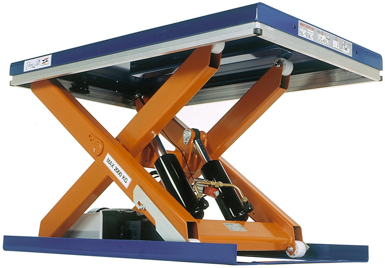
TL_2000_scissor_lift.jpg
 
Replies continue below

Recommended for you

Dear Magnusrm,
Your starting point should be better a global 1-D Beam model to check that loads & computed reaction forces are reasonable, also you can check the stress levels in the beam elements and plot shear & moment diagrams. Also life is easy regarding prescribing loads & boundary conditions, as well as joint definitions. Usiong rigid elements RBE2 you can couple displacements & rotations DOF at joints between members (ie, define multipoint constrains), remember this is internal to the FE model, not a constraint.

Once your 1-D global FE model is checked and the results are reasonable correct then you can start you detailed model: I suggest to start with Shell 2-D plate elements, forgot at all solid elements, the thickness of the plates is low compared with the length, create midsurfaces and mesh with CQUAD4 plate elements. You will need to learn how to define joints, basically using rigid elements RBE2. Do not overconstraint the structure, be soft with constraint, define spiders and prescribe the global constraint to the INDEPENDENT node.

And the final FE model could be to mesh with 3-D solid elements, here my preferral elements is the hexaedral element, of course, you can try, OK?.

Best regards,
Blas.

~~~~~~~~~~~~~~~~~~~~~~
Blas Molero Hidalgo
Ingeniero Industrial
Director

IBERISA
48004 BILBAO (SPAIN)
WEB: Blog de FEMAP & NX Nastran:
 
Hi. Thanks for the tips. I see that it would be wise to start with a much more simplified model, but the modelling is done in SolidWorks and I have hoped to save some time by just importing the step files and mesh it with CTETRA. I will try to make a 1D-model as you suggest. Would you do this in modelling with sketch / lines, or do it directly in the FEM file?
 
how are you accounting for the mechanism ? with the siccor stowed like you show, i'd expect that the weight is supported on some stops in the structure (rather then held on the actuator). the actuator load then changes the geometry of the scissors. I think you need a model for each scissor position and actuator load.

agree with Blas ... model with simpler elements (rods or beams). once you know the model is working properly, then either analyze the fttgs as separate models, or within this model.

another day in paradise, or is paradise one day closer ?
 
I dont have any support as the actuator would have to lift the table starting from this position (even though it would rest when completely stowed).
The load on the structure is by my understanding highest (by far) when it is in this position (due to the small angles).
 
1) how did you determine the actuator load ?

2) how did you determine the change in length of the actuator ?

3) it's not clear that the model shows the scissor just slightly open. my point was that with the scissor down, there should be no load in the actuator, that the scissor will rest against a stop (rather than on the actuator). it's not a big deal, a real world thing.

4) are you running linear (small displacement) model ? i don't think you are, but the point is that the actuator load deflects the scissor, so ...

5) what is the load required (to balance the scissors) at, say, 10 deg open ? the point is that at 10deg open the scissor geometry is defined, and the actuator load is whatever it needs to be (to balance the scissor). I think it's better to model the actuator as a rod, set the scissor in the geometry you want to analyze, and have the FE tell you the load in the actuator.

another day in paradise, or is paradise one day closer ?
 
Status
Not open for further replies.

Part and Inventory Search

Sponsor