Eng-Tips is the largest engineering community on the Internet

Intelligent Work Forums for Engineering Professionals

Analysis of Continuous Fixed Beam 1

Status
Not open for further replies.

Nargo7

Mechanical
Feb 27, 2020
3
0
0
US
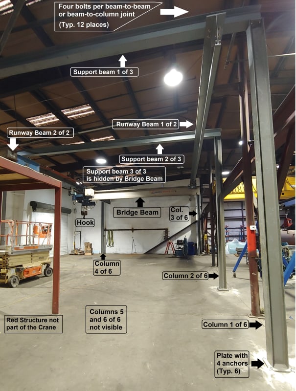
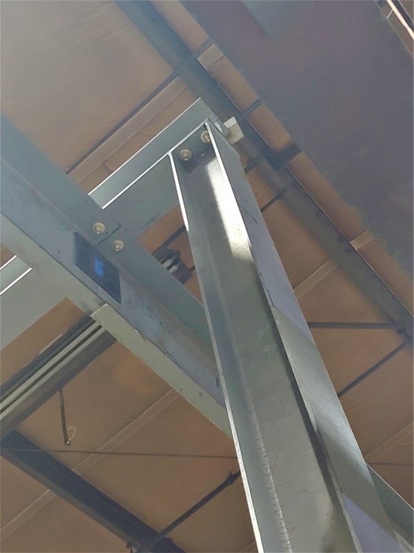
I have been assigned the task to analyze the supporting structure of a gantry crane but, being a mechanical engineer, I need to find the applicable methods to determine shear forces and moments on all elements. The supporting structure of the movable bridge beam, as I show in the picture below, is composed of two runway beams joined to three support beams, which are joined to six columns. All twelve joints are rigid, each one made with four bolts. Years ago, I calculated continuous beams using the Three Moment Theorem, but in internet I only find this method applied to beams with more than two simple supports (one of them pinned), but not three fixed supports like in this case. I don’t know how to analyze a 3D structure composed by seven rigid frames joined together, and the company where I work does not have any analysis software. My second question is, after knowing the reaction moments and shear forces at base plates of columns, I need to calculate tension forces at the anchor bolts to the floor. I will have to assume the worst concrete, 2,000 psi, as we don’t have the construction drawings of the building. Any help will be greatly appreciated. Thanks!

Crane_Arrangement_xihdxk.jpg
 
Replies continue below

Recommended for you

if your supports are fixed, then analyze each span as a double cantilever.

you can use MDM. You can use three moment equation, there are "ways" to modify the calc for fixed supports, but (IMO) each span is isolated by an infinitely stiff fixed support.

but looking at your pic, I'd say the runway beam and the support beams are continuous over pinned supports, the base of the columns are reasonably fixed.

another day in paradise, or is paradise one day closer ?
 
Looks mildly sketchy to me, but if it works...

Just because there are four bolts doesn't mean the joint will be fixed - at least not as it impacts the global analysis. I'd start by assuming the base of the columns are fixed, the beam-column joints are pinned, and the connections of the crane rails to the beams are also free to rotate. The beams are likely flexible enough to bend and twist elastically which will make them behave more like pins that actual fixed supports.

What is the goal of your analysis? Is it performing poorly due to excessive deflections/drift?


I suggest pass it onto somebody familiar with structural design. The analysis is not difficult, but unless the lift capacity is small, I wonder how the framing can maintain stable when subjects to thrust both in the longitudinal, and lateral directions. Note that I don't consider the connections are fixed, they are more like pins with limited moment capacity.
 
Are the Support Beams installed on a slope? That would mean that the Runway beam web is not plumb which would impose a torsional force in the beam which is not a fun analysis.

Let's assume that the picture is just distorted and the support beams are level. Keep it simple, Don't analyze it as a 3-D frame. Break it apart into simpler components.

Check the shear and moment in the runway beams first. You have a 2 span continuous beam with pinned supports and a moving crane load. There are several ways to analyze this but since it sounds like you haven't solved some structural analysis problems lately, then a simple beam analysis program would be good. Without that, I do have some Manders Angers Beam equations that I can try and upload later which give you influence lines for concentrated loads at different locations.

Compare your shear and moment demands on the runway beam with the capacities that you get from AISC.

Then take your reactionary loads on your runway beam and apply it to your "rigid" frame. The fixity of the support beam to the column is questionable. You say it has four bolts, but are the column flanges welded to the bottom of the support beam flange? Looks questionable.... I would analyze the support beam using a lower bound approach as simply supported. Easy!

If you want to check your column you have your vertical load. I would probably be conservative and apply a moment at the top based on an upper bound assumption of a fixed end moment for the support beam. If that didn't work out I would refine that part of the analysis.

Check your anchor bolts for moment at the base. This will be the most difficult task and most likely will give you issues with capacity. I really don't know how you are going to analyze the anchor bolts since you don't know the embedment. The embedment is everything for this check. Since it looks like those columns were installed after the building was erected, they are most likely post-installed into a thin slab on grade foundation.


I'm surprised the runway beam isn't shimmed to make it level... and if you check the beam for PL/5... that will give you an approx idea of the bending moment. The runway beam can be strutted to the column for bracing... have to be careful about the flexural stability of the runway beam for being laterally unsupported between columns. On a positive note, your load is applied below the shear centre.

The AISC has a spreadsheet for this type of problem if memory serves.


Dik
 
Nargo7,
Some things to consider in your design (beyond your direct questions).

1. Be sure to use the actual dead weight of the bridge, trolley, and hoist.
2. Use the rated capacity of the hoist and include the appropriate vertical impact factors.
3. Include in your analysis lateral and longitudinal forces from the crane (See AISC steel specification or Crane Manufacturer's specs).
4. You will have many load conditions to consider (moving load down the length and lat/long forces). Be sure to include all relevant combinations.
5. The "fixity" you mention is based on a simple plate with four bolts - there is actually a partial rigidity here - so per the others, you can assume it fixed but you must check the plate bending for these forces.
6. The plate bending, beam bending, bolt tension, etc. all will be subject to fatigue conditions - so you also have to check fatigue based on the rating of the crane.
7. The overall system, longitudinally, appears to depend only on the anchorage to the floor (vs. an X-brace between columns). This will create large tension forces in the base anchor bolts.
8. With uncertain floor concrete strength, condition, and capacity, relying on post-installed anchors with large tension forces is a concern.
9. Do you know the grade of steel you are working with?

There's more.

So if you don't know how to do the above, then you should definitely hire a structural engineer who can.

 
Here are the Anger's Influence Line Tables for a 2-span continuous beam. Sorry, I said Manders Equations previously.... I meant Angers. Brain fart.

They are useful for moving load analysis.... however nowadays, I can model a continuous beam, with material properties, section properties, truck axle spacing in MIDAS Civil and run a full moving load analysis with moment and shear envelops in less than 5 minutes so the old Angers tables don't get much love anymore.

I will correct my previous post
 
 https://files.engineering.com/getfile.aspx?folder=f2e08116-b7d1-4f18-af8a-139d95da1dee&file=A9Rqcea2t_m1t0oq_c8s.pdf
That frame looks very unstable to me. The frames I've seen before supporting bridge cranes and monorails usually have welded beam-column connections similar to moment frames. Is there a reason why you are analyzing it? We can give some general methods to perform an analysis but knowing what the issues are (if any) might help with any assumptions we would make.
 
Thank you all, rb1957, phamENG, retired13, and STrctPono, dik, JAE, and EDub24, for the fast and useful replies, which have given me a lot of information but also concerns. I tried to answer to all your questions below, but most likely some of my answers are inadequate due to lack of time to keep up with everybody. But thank you all very much anyway! And I am looking forward to continuing this thread.
1) I see that all agree that the joints between beams (runway and top support) should be considered as pinned and not fixed supports. I thought that four bolts would be enough to qualify as fixed, but after your explanations now I understand that, being those bolts so close one to the other, they provide little restriction to prevent the beam from deflecting. Three pinned supports (well, one pinned and two simple) would be easier for me as I used, 32 years ago, the Three Moment Theorem, during my only real encounter with beams.
2) rb1975, I could figure out what is MDM, Moment Distribution Method, which I briefly studied for a class assignment, 35 years ago, as Hardy Cross. But what is IMO?
3) phamENG and EDub24: the purpose of my analysis is to verify this system before initial use by us. Those six beams and six columns, plus the three motors and all accessories, were bought a couple of years ago from another company, where they were used as a gantry crane, so they were disassembled and stored by the company where I work. They were recently installed (and I was recently hired!). So, the structure was proved in the previous company, but we want to verify it, and of course to check the anchor bolts we are using, which are the same size as before because we have not modified the base plates, with the worst concrete resistance possible, 2,000 psi. This calculation of the anchor bolts is very fuzzy to me, I found a calculation in Engineers Edge website per ACI-318, it is a big formula, I am not afraid of its size, but I need to understand its different terms and we don’t have that ACI spec.
4) retired13 and JAE: The crane is rated for a live load of 6,000 lbs, but the crane catalog indicates 6,600 lbs. for the bridge beam, trolley, two end trucks, three motors, and 900 lbs for impact load, for a total of 12,600 lbs. to be supported by the runway beams.
5) STrctPono: I am sorry that, due to the angle where I took the picture, the beams seem as on a slope. They are horizontal.
6) STrctPono and JAE: Those columns were installed this year, while that building should be around 30 years old. They drilled holes in the floor and used 3/4" x 5-1/2” long anchors. As I said before, those columns, beams and motors were used by another company at another location.
7) I am attaching a picture of a top joint. The runway beam is spliced of two sections, one is 40 feet long and the other is 14 feet long. This picture shows the middle column and the splice plate, there are two plates like that one, one on each side of the web of the runway beam.
8) JAE, we could add those X braces between columns, but I would need to demonstrate their need with calculations, because this crane was used without them. And I was planning to calculate considering the worst structural steel grade, that is, A36, with 36,000 psi for yield strength.

0206201535_cvt9om.jpg

 
Nargo7 said:
I have been assigned the task to analyze the supporting structure of a gantry crane...

Have you bounded the structure's capability by assuming all members are simply supported?
If it passes... your job just became much easier.

In the USA, an OSHA static test load of 125% of rated load will have to be lifted. Test can be performed under ideal condition (no impact), but the structure has to be adequate.


[idea]
 
FYI.

Lateral loads to be considered for crane runway design:

1. Lateral/side thrust: 20% of the sum of weight of trolley and the lift weight.
2. Longitudinal/tractive thrust: 10% of the maximum wheel load.
3. Crane stop force.
 
Well, your job just became a bit easier as that runway beam is no longer continuous. It is 2 simple spans. Obviously the 40ft span will govern.

I would listen to retired13 and check the lateral loads as that whole frame seems precariously restrained as-is.

Without ACI-318 the coefficients that go into the post-installed anchor calculations will be hard to decipher. I'm going to be completely honest, I hate running those calculations as they are so tedious. Many of the adhesive manufacturers figured this out and created their own proprietary freeware to help with the task. You can check out the different programs like Hilti's Profis and Dewalt's (Powers) Design Assist. Pay attention to that control joint adjacent to the base plate. That should be considered a concrete edge and will reduce your anchors concrete breakout/edge breakout capacity.
 
Thank you, SlideRuleEra (great user name, by the way) for answering to my question, and retired13 and STrctPono for the additional post after your first one.

And I am sorry that I didn’t reply in the last two weeks, but I was working in another project, besides I wanted to work more on this one before replying. So, below are my new points:

1) I considered one pinned support and two sliding supports for the runway beam, programmed the Three Moment Theorem formula in a spreadsheet and determined the internal moment in the middle support. With it I calculated the vertical reactions at all three columns, and verified my results with formulas from a standard table of formulas for moments and reactions in continuous beams with three simple supports, by superposition of two cases: equal uniform load on both spans and one concentrated load at center of either span. All match with the Three-Moment result. But I still have to play with the spreadsheet (or check the Angers equations provided by STrctPono) by changing the location of the single concentrated load to find the position that maximizes the vertical reaction in each of the three columns (three positions total).

2) In my first reply I did not address the concerns about stability expressed by phamENG, retired13, STrctPono, dik, JAE, and EDub24. My plan is to propose to the company owner to brace horizontally the top of each of the six columns of the crane structure by welding elements between those points and the main columns, or beams depending on the location, of the building. Also, at the base plates of each of the six columns, I would add a double-T section piece clamped with two 1” anchors at each side of the plate, for a total of eight new anchors with four clamps on top of the four existing anchors. At the two columns next to the back wall in my first picture, we have 8” between the edge of the plate and the wall, so I think we have enough room for the drilling machine, but I would want to have a new clamping element added at each of the four sides of each base plate, for symmetry.

3) This structure is in Virginia, so we definitively need to comply with OSHA. I will submit a detailed analysis to a hired-by-hours competent structural engineer for review. Before that, my boss and I are planning to verify my load calculations by paying $79 for one month of use of an FEA software at a website (I think I should not advertise its name).

4) Thank you, retired13, for the specification of the horizontal forces. After I calculated the vertical reactions, I knew I needed to consider the moments at the base plates (with only vertical forces at the columns, theoretically we would not need anchor bolts at all), so I calculated the horizontal force after the sudden stop of a 6,000 lb. live load traveling at 100 ft/min (the speed of the end trucks) and swinging at the end of a 10 feet long cable (calculated swing angle 5.3°) and got a horizontal force of 559 lbs. at end of the cable. But, to calculate the crane stop force, I will call the crane manufacturer to get either a reasonable time or braking distance for the 5,700 total weight of the trolley, bridge beam and end trucks, the crane catalog does not indicate this information; with that distance or time I can calculate the brake force, add to it my 559 lbs., add also your item #2 for longitudinal thrust (10% of 12,600 lbs. to include the 900 lbs. impact indicated by the manufacturer) and split that total in half between two runway beams to obtain the total horizontal force along each runway that creates moment in that longitudinal vertical plane. That moment I would distribute it evenly between the three columns (one-third for each column), because the runway beam would be considered infinitely stiff in the axial direction. But your item #1, that 20% lateral thrust I would apply it in its entirety to each column and creating moment in a vertical plane normal to the previous one, because when the bridge crane moving a load is passing directly in front of a particular column, the contribution of the other two columns to support this horizontal load is negligible due to the very low moment of inertia of the runway beam respect to the vertical axis. This is how I understand this situation. The lateral 20% force of #1 will be distributed as a concentrated load with the Theorem of Three Moments, as described in my point #1 above to find the critical location, its bending stress would be combined with the bending stress due to weight, resulting in one quadrant of the runway beam subjected to two tensile stresses, on the opposite quadrant to two compression stresses.

5) Thank you STrctPono, for the indication of the Hilti and Dewalt calculation tools. My boss and I were hesitant of buying the ACI 318, $274 just to use Chapter 17, “Anchoring to Concrete”. We are a manufacturing company of mechanical equipment that does not use concrete at all.
 
Nargo,

Thanks for taking time to respond our suggests and comments. Seems you have the situations well handled. One more reminder: if the crane wheels have double side flanges (like the pulley), then the lateral thrust will engage two columns instead of one. The crossed out comment does not valid for underhung crane, please ignore.

But your item #1, that 20% lateral thrust I would apply it in its entirety to each column ...
In your case, you can distribute the thrust on two columns, as the load will be passed through the topmost framing beam (in the transverse direction), thus engage the two columns at its ends.

 
Nargo7,

After you posted a picture of the runway beam splice on Feb. 27th, I responded by saying that your job just became easier as you do not need to analyze the runway beam as a 2-span continuous but rather 2 individual simple spans. You will be non-conservative for the maximum positive moment demands on that runway beam if you proceed with your results from the three moment theorem approach.
 
The above responses commendably attempt to provide an impromptu education in structural engineering.
That is difficult to do in an on-line written forum. This work really should be completed
by a structural engineer unless you have a structural engineer to provide in person guidance and supervision.
 
retired13 covered the issue that popped out at me....lateral thrust. The crane does not look like it has a high capacity, but running it perpendicular to the bents with max load is going to throw a domino affect into the system.

 
Status
Not open for further replies.
Back
Top