Continue to Site

Eng-Tips is the largest engineering community on the Internet

Intelligent Work Forums for Engineering Professionals

  • Congratulations cowski on being selected by the Eng-Tips community for having the most helpful posts in the forums last week. Way to Go!

Analysis of Hollow Circular Disc/Node connecting beams 3

Status
Not open for further replies.

Arbu

Structural
Mar 25, 2018
69
Dear All,

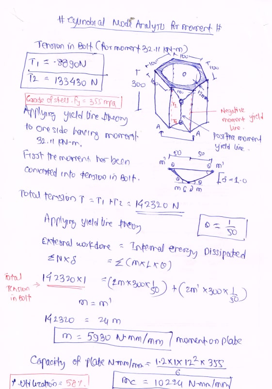
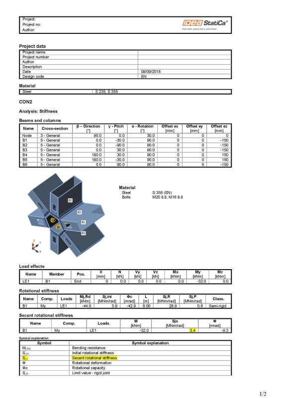
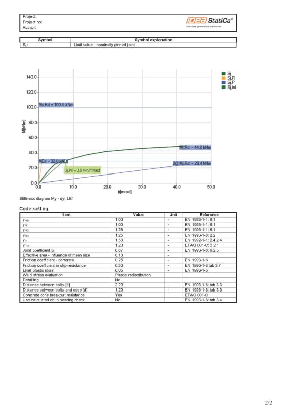
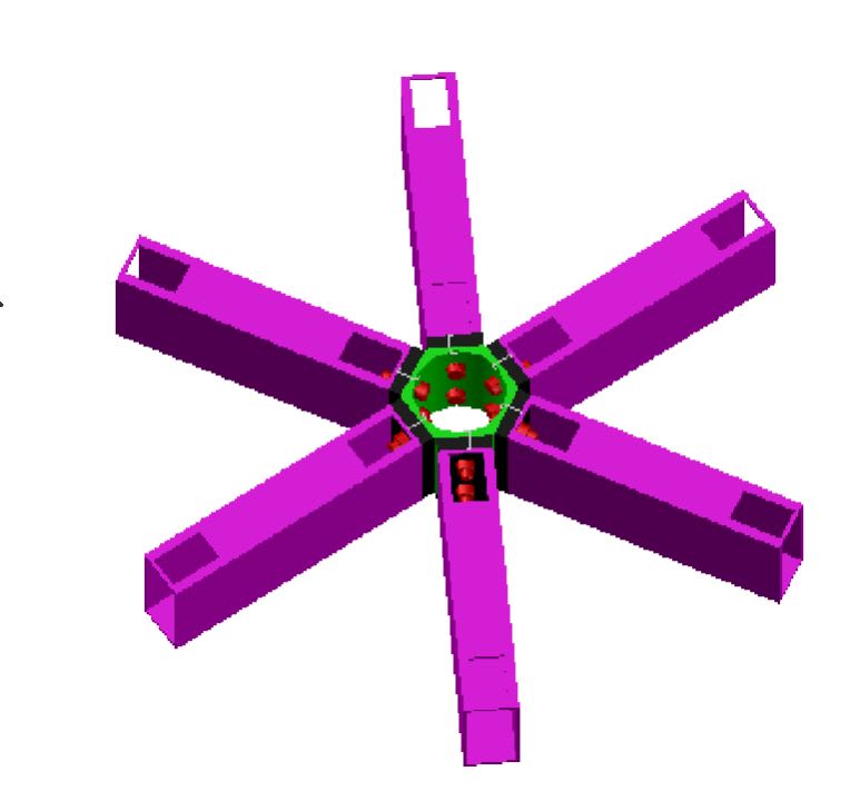
I am designing a Steel Skylight in which beam supporting skylight has been connected with each other by a Hollow circular disc As shown in image below. All member are RHS/Tube 160x80x5 mm. each member is carrying major moment, Major shear and axial Compression/Tension. I am looking for some analysis method for the disc/Node connecting beams. Please suggest some method.
Disc_njosrk.jpg


regards,
SigmaEng
 
Replies continue below

Recommended for you

you could say each leg supports 1/6th of the load on the window, and load the leg with a variable distributed load. What of thermal loads ?

btw, you could avoid those cut-outs (for access to the nuts) by using "heli-coils" (threaded inserts).

another day in paradise, or is paradise one day closer ?
 
I don't see any disk, just a tube with circular inside and hexagonal outside.
Anyway-
If the whole problem is symmetrical, with equal loading from each tube, you can sum moments about different cross sections through the center and find moments and hoop stresses in that element.
Roark's Formulas for Stress and Strain includes load cases for N radial loads on a circular ring that might be of help.
If you can reasonably show that it is adequate for equal radial loads or equal moments from each arm, can you then deduce it is adequate for lesser, but unequal, loading from each arm?
And can you detail it to use a pinned connections to eliminate the moments?
 
these are special connectors used for free form spatial roof structures
known as 'MERO' Type connectors

see here
 
Dear JStephen,

I cannot Make it hinges, there will be instability.


Dear All,


Can I analyse it for moment by Yield Line theory. Every side of Cylinder I will consider plate fixed on edges and three yield line one positive and two negative on support. Please see the attached Image. If possible suggest possible pattern of yield line.
Capture_dq2aj5.jpg
 
We usually design the node to be 'strong' enough..this means the wall thickness is 'thick'

more crucial is the connection itself....bolts are pretensioned but still connection is not fully rigid because there can be gaps between member and node ...
so in the global model the connection should be flexible ( not rigid...not hinged) ...some type of rotational spring stiffness
the yield line method is used to design the end plate of the member...but of course you can use it too to check the node

but nowadays 3D FE method can be helpful for node design
 
Dear Klaus,


thank you for your suggestion.

I Know ANSYS APDL also, but How to provided restrains/Supports. As the cylinder itself supporting 6 beams, here I will provie support to cylinder while doing analysis in FEM. If anyone have suggestion please let me know. Might be this will be possible in ANSYS workbench but i am not familiar with Workbench.


Dear All,


Sorry for delay, I was posted on other project, now I came back on the same.

I did Analysis of Node cylinder and Bolts in Ideastatica Software. Its showing 12 mm thick node is safe in Strain (< 0.2 %). And also I got stiffness of joint from Ideastatrica (M-Phi) curve. And for verification of thickness I analyzed one side of cylinder by Yield line theory. I am attaching the results of Yield line theory and Stiffness of joint. I have following two doubts.

1.0 My approach and yield line pattern is correct or there will be some change in yield line/approach as we are having different tension in two bolts.

node_peliq1.jpg


2.0 The span of beams is 9 m and we have 3 nodes in one span, I am having a doubt of extra deflection due to this node, as node connection is not rigid and its semi rigid. Is it okay if I apply the Secant Stiffness (Sjs) obtained from attached image in STAAD pro to every memeber (As end release spring) those are connected to node to get the probable deflection due to nodes.

nodestiffeness_Page_1_ce8pni.jpg
nodestiffeness_Page_2_f1lpol.jpg


Please check and guide me.
 
Does the IdeaStatica Model have contact surface between beam and Node ?
Model looks interesting...could you provide statica input file ?
 
Dear Klaus,

Ideastatica is having all the capablity for modelling. Any plate and beam if you are connecting then it will treat those surfaces as contact element and it will not allow peneration. I am attaching model for your reference.

Dear all ,

please comment on my assumptions and suggest some method to verify manually.


Regards,
Sigma

 
Status
Not open for further replies.

Part and Inventory Search

Sponsor