Eng-Tips is the largest engineering community on the Internet

Intelligent Work Forums for Engineering Professionals

Analysis of sloped, irregular, wooden diaphragms

Status
Not open for further replies.

DetroitJon

Structural
Apr 26, 2016
6
0
0
US
Long time reader, first time post. Nice to join you all!

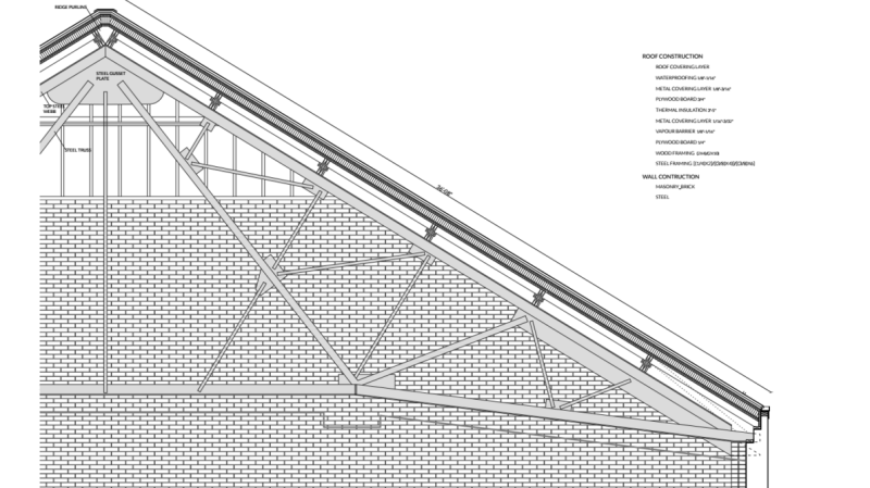
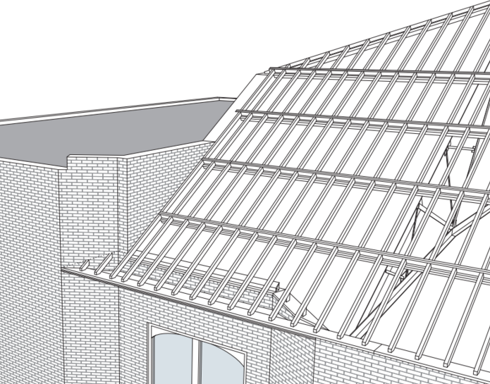
I'm looking at a rehab of a 110 y.o. social hall. The main room is 60 feet wide and covered with a sloped (6.8/12) roof. The structure is new to me. Massive steel trusses cross the 60' span every 16 feet (they're very rigid). Doubled 2x10s (I'll call them girders here) span the gap between trusses and are spaced every 7 feet from the ridge down the top of the unreinforced masonry wall. The girders are mounted on an angle, with their strong axis running perpendicular to the roof sheathing. 2x6s @ 16" OC run parallel to the steel trusses from girder to girder and the whole thing is sheathed with 23/32 OSB, long side running parallel to the ridge. Location is in Detroit so nothing special with seismic or wind.

I'm guessing the current construction doesn't meet code. It was done as an emergency keep it dry sort of maneuver. I'm having a hell of a time modeling this though. Ideally, we can add some sheathing to the top side, perhaps with a 3" layer of foam in the middle and maybe some doubled 2x6s laid flat at the sheathing seams.

Ok, so here are some questions. How do I model this? I'm imagining using the supports on the truss as my boundary conditions (pinned) and then trying to characterize the two-way bending and sheer stiffness of each bay (16'x7' OSB and 2x6 construction). Then I just constrain my shell element to the steel truss (not moving) along the short side and to the girder (which does bend along the strong and weak axis) along the long side. I can then play around with the shear and bending stiffness of the bays by looking at different construction options to get to something that's strong enough and doesn't rely too heavily on transferring loads through shear to the top of the masonry wall.

Does this seem like a reasonable approach? Are there any software packages out there that will do this for me? Especially concerned about that multi-dimensionality of the OSB, taking advantage of the slope, nailing patterns...etc. So far, I'm looking at a full FEM workup in Matlab or modeling each bay a as big truss in Risa that approximates the shear and bending stiffness. Is there a way to distribute the effect of the girder across the roof diaphragm so that I'd be looking at a single 16'x35' plate instead of 7 separate plates intermingled with the girders?

Found that Risa truss suggestion on this forum, hoping to dig up some other interesting analysis methods here!
 
Replies continue below

Recommended for you

i don't see the irregularity of the diaphragm from your post, but I may have missed it...sounds like a nice rectangle to me
i'd probably start with the sheathing and just work through each element one by one:
sheathing, which is probably ok,
2x6@16 with connections which might be ok, but might take a lot of wind
2-2x10s with connections which also might be ok but take a lot of wind, check biaxial bending
then check the trusses.
 
T,
I'm thinking that the "irregularity" is the two planes of the roof (one on each side of the ridge).

DJ,
I assume there is no ceiling or no opportunity to add a ceiling?

What is it that you are trying to get the diaphragm to do, span "horizontally" to get the wind load out to the side walls or brace the top of the unreinforced masonry walls?

How long is the building? 60 ft truss spans and trusses space at 16 ft but.... how many?
 
T,
That's where I started. Problem is, the 2-2x10s don't work. They barely carry the dead load with that method and after doing that calc I was worried the structure would collapse. After some thought, I figured the girders are picking up some extra strength from two different sources: additional effective bending depth from the sheathing (sort of like a T section in concrete) and the in-plane shear resistance of the sheathing (is resisting gravity loads since the roof is sloped). I've always ignored these effects, I don't know if they're included in any code.
HB,
The roof does have two sides but overall it's pretty normal. I need to approximate the shear behavior of a diaphragm section as it applies to gravity loading and since it has the girders providing in plane assistance, I've got to add that in somehow. Those girders in my diaphragm are the irregularity. If I get a 20 psf live roof load to work, I'm guessing I can get the wind to work out (the steel can collect the lateral and get it down to earth). There are 4 steel trusses for 5 bays all together. The end ones are a bit shorter so I'm designing to the 16' section imaging that the diaphragm is fixed around the edge of the 16'x35' bay. Of course, the diaphragm has to be strong enough to carry the reaction from one bay to the next.

There's a bit of voodoo that happens with sloped roofs and I'm gonna get to the bottom of it. I just remembered Abaqus/CAE, pretty sure I could work up a solution there. Would love to be able to run this by hand instead...
 
DetroitJohn said:
Would love to be able to run this by hand instead...

What ever is stopping you? I would absolutely run this by hand. And if it doesn't work by simple hand analysis, start reinforcing things. Leave the diaphragm voodoo to Voldemort and FEM college professors. Your insurer approves this public service announcement.

I like to debate structural engineering theory -- a lot. If I challenge you on something, know that I'm doing so because I respect your opinion enough to either change it or adopt it.
 
if the (2)2x10s "barely carry the dead load", there is no way I can imagine that the sheathing would gain enough additional capacity to make them work. Reinforce them...it's straightforward. I wouldn't even investigate it as an option.
if the 2x6s don't work, reinforce them, it's simple.
23/32 OSB should be plenty strong for that roof, assuming indeed it is OSB and not some furniture grade waferboard......I'd look for mill stamps. APA-EWS can be very helpful identifying wood sheathing etcetera. Might need to add nailing for your diaphragm.
Not sure, but i'm thinking the wood, certainly the OSB is recent vintage compared to the 110 year old building. If the (2) 2x10s are 110 years old, I'd expect them to be net 2" by net 10" and not 1.5x9 1/4 or whatever....same with 2x6s. Some people think older wood is gooder wood.
It's possible only the trusses are 100 years old. Are they riveted? This is where, I'd expect the engineering work to be. Glad to hear their "massive" and "very rigid" ... would love to see photos details of these trusses.
 
Are the trusses attached to the columns to form a rigid frame sort of thing? I doubt 110 years ago that anyone had even thought of a wood diaphragm. Typically the steel framing stood on it's own, with the wood framing and decking just delivering the load to it.
 
KK: Thanks for reminding me of my FEM professor! Might hit him up for a nailing pattern on this one. I am getting close to working out a solution by hand so I have a pretty decent sense of how this is working out. The diaphragm has huge in plane shear stiffness on account of the short span (16') the long effective depth (35'). As long as the stiffness of the diaphragm is is a lot more than the major axis bending resistance of the girder, the load can be divided between the two geometrically. A 12/12 roof with a rigid shear diaphragm, for example, would pass 2^-.5 of the gravity loads to the major axis of the girder and the same amount to the diaphragm. Wind loads act perpendicular to the surface and are carried entirely by the girder in major axis bending but since there's around 10psf wind here, I get more from the diminished live load [20*(31'/35')*cos(29.44)] = 15.4 psf.

&Triangle: So that gets me to the first part of the solution, redesigning the girders for the sloped component of the dead load plus a 16 psf live load working on the major axis, probably constrained by an L/180 live load deflection. The deflection will be greatly lessened by running the extra wood above the sheathing with a break at the center of each span, creating a fixed support condition. To avoid shear concentration where the reinforcement breaks midspan, and to allay my fears that the 2x6s are forming a compression strut that's stiff enough to put load into my precious girder fibers, I'm going to add flatwise K bracing on the face of the diaphragm running diagonally down from the center of each girder to the steel truss. Not sure if I need to run a spine along the truss on the top side of the diaphragm. Will have to check shear flow crushing the wood at the truss connection. The voids between all this jazz will be foam and then another layer of sheathing is going on top. Also, I'm attaching some drawings for your pleasure, I'll get some pictures for you all shortly. Long story short, one half of the roof is 110 years old and not in the best shape. The other half is brand new (un-engineered thanks to an over zealous roofer) and built to a slightly lower standard than the original. Both sides require reinforcement.

@Sawbux: The trusses sit on massive masonry pilasters. I did a quick graphic statics check on them, lateral isn't a factor as long as the trusses can collect the load. And I'm quite certain diaphragms have been well understood since at least Euler, though it seems like the engineers now, as in back in the day, left this to the roofers to figure out. I'm willing to tell a roofer he's wrong, but I'm not going to do that based on an overly simplified model that doesn't take into account some obvious physical realities that help the structure and that any decent roofer has a intuitive feel for.

@HB: You're right about this not being irregular, I mean I suppose the girders contribute a little to the shear strength, but it's tiny. Show me a project that isn't at least a little unusual and we'll call it the exception that proves the rule.
roof1_ciaqts.png
roof2_blobsx.png
 
OP said:
The diaphragm has huge in plane shear stiffness on account of the short span (16') the long effective depth (35').

Based on your sketch, There does't appear to be any in plane shear connection between the diaphragm and the truss top chords. If that's true, then your diaphragm would really span 80'. And that would only be if the diaphragm had continuous chords which appears unlikely.

Are their sag rods connecting the girders at some interval? You could do something with that.

OP said:
And I'm quite certain diaphragms have been well understood since at least Euler

I doubt that. To this day, we're still having a hard time convincing Australia to believe in sheathed diaphragms (at least in steel).

I like to debate structural engineering theory -- a lot. If I challenge you on something, know that I'm doing so because I respect your opinion enough to either change it or adopt it.
 
Are the doubled 2x10's 2-span, with the end joints staggered? Back in the day, longer lengths were available and maybe they got 32 footers and did 2 truss bays with them. Get some negative bending capacity with that arrangement which might make them work?

Is there some bottom chord bracing on those trusses? Check possible wind uplift, although roof may be heavy enough to negate.

If diaphragm doesn't work, then maybe think cable bracing between trusses. Likewise on 2x10's, you could reinforce with cables, harped to reduce dead load. Could do multi-span full length of building as economical strengthening method.
 
Status
Not open for further replies.
Back
Top