DetroitJon
Structural
- Apr 26, 2016
- 6
Long time reader, first time post. Nice to join you all!
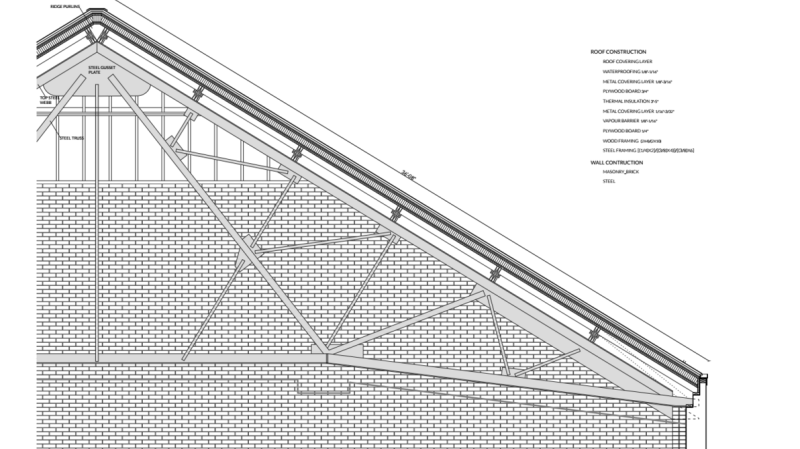
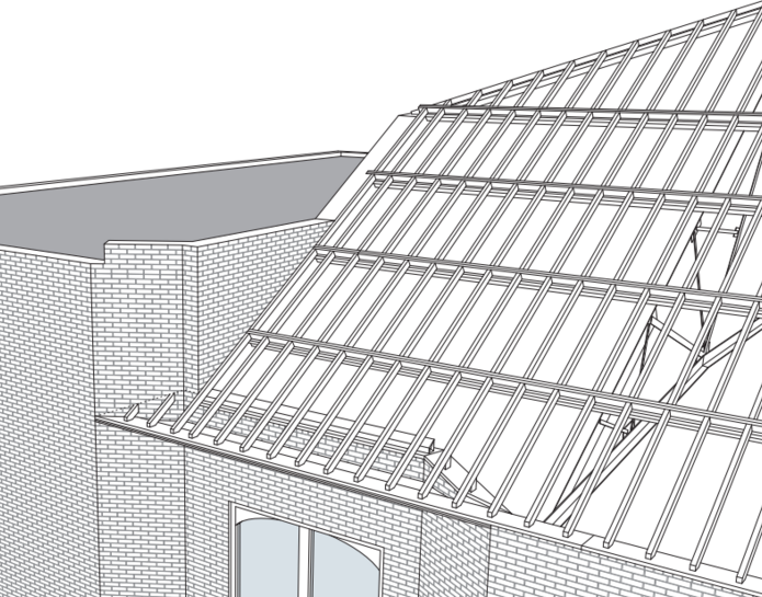
I'm looking at a rehab of a 110 y.o. social hall. The main room is 60 feet wide and covered with a sloped (6.8/12) roof. The structure is new to me. Massive steel trusses cross the 60' span every 16 feet (they're very rigid). Doubled 2x10s (I'll call them girders here) span the gap between trusses and are spaced every 7 feet from the ridge down the top of the unreinforced masonry wall. The girders are mounted on an angle, with their strong axis running perpendicular to the roof sheathing. 2x6s @ 16" OC run parallel to the steel trusses from girder to girder and the whole thing is sheathed with 23/32 OSB, long side running parallel to the ridge. Location is in Detroit so nothing special with seismic or wind.
I'm guessing the current construction doesn't meet code. It was done as an emergency keep it dry sort of maneuver. I'm having a hell of a time modeling this though. Ideally, we can add some sheathing to the top side, perhaps with a 3" layer of foam in the middle and maybe some doubled 2x6s laid flat at the sheathing seams.
Ok, so here are some questions. How do I model this? I'm imagining using the supports on the truss as my boundary conditions (pinned) and then trying to characterize the two-way bending and sheer stiffness of each bay (16'x7' OSB and 2x6 construction). Then I just constrain my shell element to the steel truss (not moving) along the short side and to the girder (which does bend along the strong and weak axis) along the long side. I can then play around with the shear and bending stiffness of the bays by looking at different construction options to get to something that's strong enough and doesn't rely too heavily on transferring loads through shear to the top of the masonry wall.
Does this seem like a reasonable approach? Are there any software packages out there that will do this for me? Especially concerned about that multi-dimensionality of the OSB, taking advantage of the slope, nailing patterns...etc. So far, I'm looking at a full FEM workup in Matlab or modeling each bay a as big truss in Risa that approximates the shear and bending stiffness. Is there a way to distribute the effect of the girder across the roof diaphragm so that I'd be looking at a single 16'x35' plate instead of 7 separate plates intermingled with the girders?
Found that Risa truss suggestion on this forum, hoping to dig up some other interesting analysis methods here!


