Continue to Site

Eng-Tips is the largest engineering community on the Internet

Intelligent Work Forums for Engineering Professionals

  • Congratulations KootK on being selected by the Eng-Tips community for having the most helpful posts in the forums last week. Way to Go!

Anchor Bolt Design for Thrust Block Foundation Pedestal 1

Status
Not open for further replies.

oengineer

Structural
Apr 25, 2011
708
I am working on the design of a concrete pipe support pedestal. The pedestal is supporting a 16" diameter pipe. The pipe is attached to a 90 degree elbow with a pressure of 130 psi. My pipe support is located above grade.

The resultant thrust force due to the 90 degree elbow is 37 kips ( Fx =Fy = 26.1 kips [force components]). This is based on the equation in the image below:
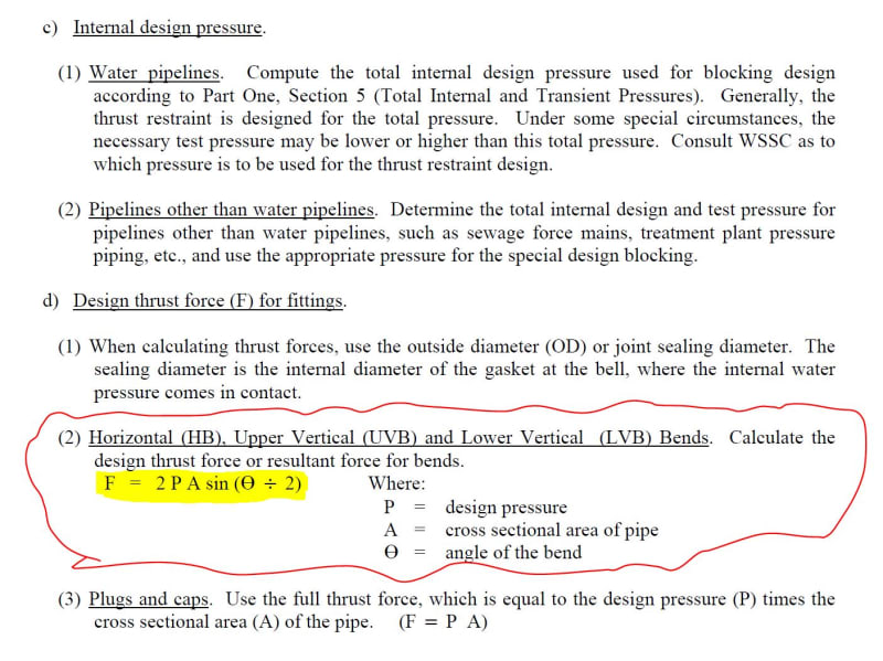
thrustblock_hjg3dt.jpg


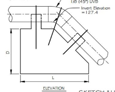
I have obtained a sample plan sheet of thrust blocks.

See this link for the example thrust blocks:
Based on the example drawing, it seems to me as if anchor bolts are not considered when design thrust block supports. Would this be an accurate statement? Since my 16" dia pipe is above grade, would my design be under a different criteria?

The initial concrete pedestal detail that I am revising has an anchor bolt shown.
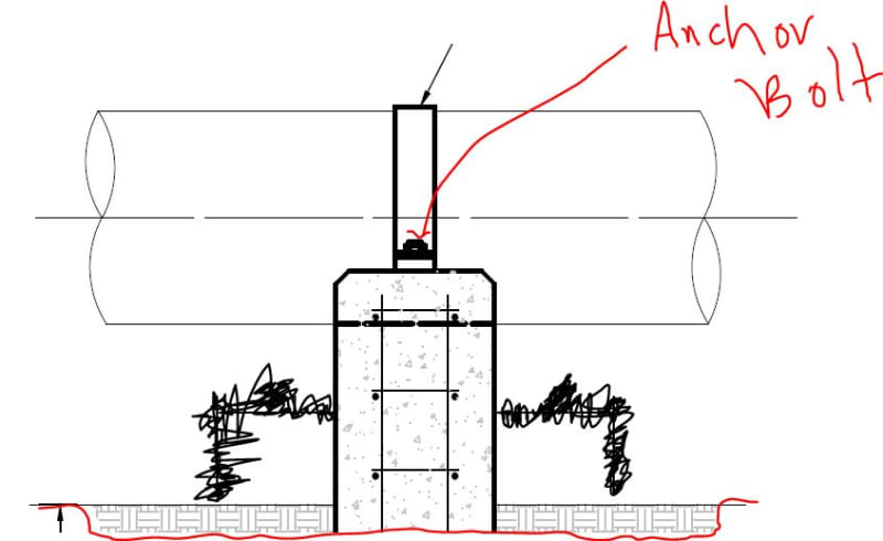
thrustblock_ancchor_cyfxm8.jpg


There are initial a total of two anchor bolts (1 on each side of the pipe) that would be resisting a horizontal force of 26.1 kips coming thru the pipe.


I initial would think that the anchor bolts need to be able to resist the thrust forces applied by the elbow ( Fx =Fy = 26.1 kips [force components]). Is this accurate?

Suggestions/comments are appreciated.
 
Replies continue below

Recommended for you

Additionally I guess the clause d (2) is generally for the underground piping not for the above ground piping. Again this clause is used for the piping that the pressue is not contained by the pipe wall. Again ask for clarification.
 
saplanti said:
Oengineer, you do not mention what type piping and fittings that were used in your application and the design code. In case the piping is fully welded/flanged and you do not use expansion joint in the application the pressure is already taken by the pipe wall there is no need for pressure thrust design. However the above ground pipe may be subjected to thermal loads. In case there is not big differantial temperature to introduce axial thermal load and/or fluid excited loads I would not worry about axial thrust at all.
If I were you I would check with the piping designer for the thermal or fluid excited loads at the specific supports or ask for clarification for the issue.

The fluid going through these pipes is water. The pressure is at 130 psi. All the pipes that I am designing are above ground.

The civil engineer provided me the forces at the elbows based on the equation in my original post.
 
I think you need something like this at the top, but for a 90 bend.

Vertical_Pipe_Support_obf4wt.jpg


Also, you need a thrustblock down at the bottom to spread the load out below grade, unless you think the soil can handle that 26.1 kips going into it.
 
I’m with Saplanti - normally the pipe thrust is resisted internally if the joints and the pipe itself can resist the loads. The forces are equal and opposite and no load is transferred to the supports.

Water hammer during startup or other surges may have a different effect.
 
This stuff gets complicated. I think that JLNJ and Saplanti are correct for continuous pumping, but as they mention; not the startup and shutdown condition.

My understanding is that the biggest thrust force happens when a pump rapidly shuts down such as during a power outage. The startup isn't quite as bad since it takes a few moments for a pump to crank up the RPMs. The pressure wave moves in both directions, so a single thrust block might have straps for the tension and a big concrete block to spread out the compression load. I could be wrong, but I thought it was easier to design for tension/compression; than trying to pass shear though anchors.

I think all the varying opinions on this thread would lead me to ask the H&H or wastewater engineer for what direction they want their pipes restrained....
 
Oengineer, we provided information with our best guess even without knowing the piping arrangement. In case the civil engineer responsible on what you are doing, follow his/her instructions. If you are responsible and liable, ask for clarification.

Most of piping/support fail for not asking clarification and using other's knowledge without reasoning. It seems that it created question in your mind and you cannot find the answer with reasoning. What would you do? Follow unreasonable instruction.

Hope you will find the answer that you are looking for.
 
There seem to be some misconceptions here about the direction and magnitude of the thrust force the OP is dealing with.

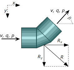
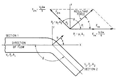
First, the direction of the resultant thrust force is not along the pipe, but to the outside of the elbow and is oriented at mid-angle. See this free body diagram that I borrowed from EngineeringToolBox.com:
pipe_bend_forces_2_d9ci2q.png

Unfortunately, they didn't draw Ry and R at the correct angles, but it's close enough for talking purposes (I will look for a better diagram). It is also important to note that for a partially to fully restrained piping system, many of the individual force vectors (which do align with the pipes) will cancel out due to equal and opposite force vectors at the previous or next elbow.

Second, while F = 2*P*A*sin(theta/2) is correct, this formula by itself is not enough. Two more things need to be considered: design pressure and safety factor.
- The OP gives a pressure of 130 psi, but is that the maximum operating pressure, the pipe pressure class, the test pressure, or the maximum transient pressure? The maximum operating pressure had better be the smallest of the four, so it's not what we design to.[smile] Depending on the client I am working with, the test pressure may be the same as the pipe pressure class or it may be up to 50 psi more. Transient pressures are usually not an issue in well-looped water distribution systems but might be an issue in a transmission main or long, non-looped plant planting. However, it's always best to deal with the transients first (e.g. surge tanks) and not let them overwhelm the thrust design. So, in general, thrust restraint should be designed for the test pressure.
- The normal safety factor for thrust restraint design is 1.5. I don't know why 1.5, but that is the standard of practice (there is a thread on this subject here: So, let's recast the thrust restraint formula like this: F[design] = SF*2*P[test]*sin(theta/2)

The best treatment I have found on the subject of thrust restraint is from the Ductile Iron Pipe Research Institute: and look for "Thrust Restraint Design for Ductile Iron Pipe" partway down the page. This document focuses on buried DIP, but the principles apply to all pipe types and to above-ground piping. The only thing this document does not cover with respect to above-ground piping is forces due to thermal expansion and contraction.

Here is one more relevant thread:
Fred

============
"Is it the only lesson of history that mankind is unteachable?"
--Winston S. Churchill
 
Well, the best diagrams I could find with a quick Internet search are the ones in the DIPRA document I referenced above.

This diagram is useful, if you remember that their theta is not the same theta we use in the thrust formula (we use the deflection angle of the fitting and not the subtended angle) and their alpha is half of the deflection angle assuming a constant diameter (for their change in diameter, the angle of the resultant will differ):
29_x2iy5s.jpg


============
"Is it the only lesson of history that mankind is unteachable?"
--Winston S. Churchill
 
Status
Not open for further replies.

Part and Inventory Search

Sponsor