Continue to Site

Eng-Tips is the largest engineering community on the Internet

Intelligent Work Forums for Engineering Professionals

  • Congratulations KootK on being selected by the Eng-Tips community for having the most helpful posts in the forums last week. Way to Go!

Anchor bolt for skid base.convertion of moments into tension force

Status
Not open for further replies.

anupriya123

Structural
Jun 14, 2016
12
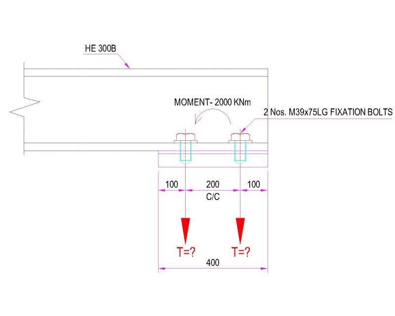
Im designing a Anchor bolt for skid base. There is a moment in the anchoring location.
How to convert the moments into tension force. I have attached the image. Please help.
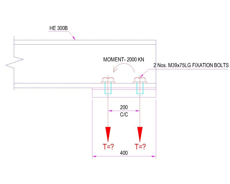
fdn-Model_vxxlti.jpg
 
Replies continue below

Recommended for you

Not much thread engagement, and a mighty difficult threaded hole to machine as drawn.
 
@desertfox

A bolt can be loaded in one of three ways mentioned below.

Tension
Shear
Combined Shear and Tension

But my doubt is how to convert the moments into tension.


@Tmoose

You mean to say need more thread length?
 
Hi

Under the link I gave you earlier scroll down strength of joints withstanding bending forces and it covers your situation.

“Do not worry about your problems with mathematics, I assure you mine are far greater.” Albert Einstein
 
@desertfox

In the link which you gave give the detail of force to moment conversion. It gives resulting tensile bolt stress from the applied vertical load.

But in my case i dont have force. I have only moment. how to convert the moments into tension.
 
Hi

The link I gave you shows the forces Fh and Fv creating moments about the bracket and resolving them into tensile forces in the bolts.

Where does the force act in your situation that generates the moment.

“Do not worry about your problems with mathematics, I assure you mine are far greater.” Albert Einstein
 
2000 kN is a force, not a moment. A length to the point of force application is required, and the units would be kiloNewton meters or something similar.

 
@desertfox

If i apply the formula given in your link the tensile force on 1st bolt comes 6000 KN. It does not seems correct.

If there are x bolts( numbered n = 1 to x). Then the tensile force withstood be each bolt is designated Fnt i.e F1t,F2t, F3t....Fxt
A selected bolt (n) withstands a tensile force of Fnt = ( Fv. Rv + Fh. Rh) . Vn / (V12 + V22....Vx2 )

Vn= 0.3m
V1 = 0.3m
V2 = 0.1m

Fv. Rv + Fh. Rh = M = 2000 KNm


Fnt = 2000 . 0.3 / (0.3^2+0.1^2) = 6000 KN ????

Will it create such a huge 600 Tons of tensile force in a single bolt???

bb_ffmjki.jpg


@Tmoose Its moment only. Unit mistake in the image.
 
Hi

your calculation is incorrect because you are using Fv and Fh but you haven't told us where or what the forces are on your joint to create the moment you are using, so what you have done is completely wrong, I suggest you get some help from a senior engineer.

“Do not worry about your problems with mathematics, I assure you mine are far greater.” Albert Einstein
 
@desertfox

Dear desertfox Thanks.

Thats why i said that formula is not applicable for this moment.
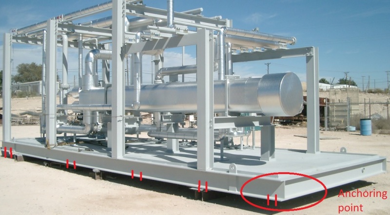
These moment of 2000 KN is created by some equipment and columns resting on the skid frame. Skid will look like the below image. It is not actual model. My model will look like this one. This skid will be anchored to another steel frame in Ship.

The reaction is taken from STAAD analysis output. it is Mz.

Vn= 0.3m
V1 = 0.3m
V2 = 0.1m

Fh.Rh = M = 2000 KNm

Fnt = 2000 . 0.3 / (0.3^2+0.1^2) = 6000 KN ????

Will it create such a huge 600 Tons of tensile force in a single bolt???

skid_gndiep.jpg


@robyengIT

Dear robyengIT Thanks for your calculation. But you assumed tension upward in 1 bolt downward in another bolt. but actually both the bolts will subject to tension in one direction. see my image.
 
Hi

Well you might of known the formula wasn't applicable but from your original post how was I supposed to know that.
If you gave all the correct information at the start we wouldn't be wasting our time and yours.
Sadly I cannot mind read!

“Do not worry about your problems with mathematics, I assure you mine are far greater.” Albert Einstein
 
@desertfox

Dear desertfox sorry. If u feel i wasted ur time. In my first post itself i posted the image. where a beam anchored on bottom. And mentioned its a skid base anchor. But in your link beam connected to column side.

What wrong info I provided?
 
Hi
Your post shows a beam over hanging two fixings and a moment of 2000kN which is actually only a force, I took it that the force was acting on the beam as a cantilever and the bolts resist the cantilever action which is why I directed you to that site.
I have asked several times where the forces act along the beam to generate your moment on the sketch but I haven't had a clear answer but now after several days we get a full photograph of a frame which changes the problem dramatically, explain to me how from your sketch I'm supposed to envisage not two anchor points but several along a long frame, look at your first sketch the frame could be up in the air resting on four columns but it clearly isn't.

“Do not worry about your problems with mathematics, I assure you mine are far greater.” Albert Einstein
 

Thanks desertfox

I would like to explain more. After I posting photograph of the frame no change in the problem. You still not understand the problem. 2000KNm moment is not on the entire frame. It is only at the end point of the skid. Every anchor point has moment. What i highlighted is maximum moment. If the bolt design is ok for that critical end point which i highlighted then no issue for other location.

After analysing the structure in software we will get force and moment at each anchoring point. We have to check the bolt design for critical anchoring location. So i posted the critical anchoring point location drawing on my 1st post. But 1st time when a person see such a drawing they may thing beam resting on column. Thats my mistake Sorry for that.
 
I'd be asking yourself why you are getting a moment (and a large moment at that) in the location in the photo.

It looks like a nominally pinned connection to me... But what do I know. As someone else noted, you should discuss your analysis assumptions with a senior engineer, you likely have something else wrong along the way in getting to this point. Your member for example doesn't appear to be of a size to even support a moment of 2000kNm,but hey what do I know.
 
If there is a huge moment as shown, and the beam and plate are sort of rigid, both bolts will be in tension.
But the proportions shown suggest that the bolts will strip out of the plate before the joint reaches equilibrium.

I surely haven't seen every possible skid base anchor detail, but that is one of the worst I have seen.

You need to get help, where you are, from a more senior engineer, who understands what you are trying to do.


Mike Halloran
Pembroke Pines, FL, USA
 
"After analysing the structure in software".....

Are you setting boundary conditions at each anchor point as initially perfectly flat and colinear with all the others?
And then solving for what each bolt would have to do to enforce that (unrealistic) condition?

I'd make one bolt of the pair out of rubber at each anchor point, and see what the vertical deflection is at the rubber bolt to get an idea if the Hbeam is large enough, or the anchor points are in the right places, close to the loads applied to the Hbeams .

With single bolts/simple supports I'd expect the moment at those end pads to be ~ zero, as others suggested.

At the real installation what will the anchor point detail be?
- Each H beam flange fully grouted in place ?
- Shimmed and grouted just at the anchor points ?
- Bolted down directly to a concrete floor or foundation block?
 
Status
Not open for further replies.

Part and Inventory Search

Sponsor