Continue to Site

Eng-Tips is the largest engineering community on the Internet

Intelligent Work Forums for Engineering Professionals

  • Congratulations KootK on being selected by the Eng-Tips community for having the most helpful posts in the forums last week. Way to Go!

Anchor bolt for skid base.convertion of moments into tension force

Status
Not open for further replies.

anupriya123

Structural
Jun 14, 2016
12
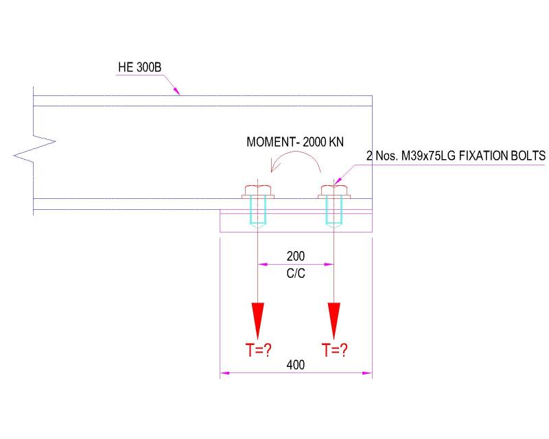
Im designing a Anchor bolt for skid base. There is a moment in the anchoring location.
How to convert the moments into tension force. I have attached the image. Please help.
fdn-Model_vxxlti.jpg
 
Replies continue below

Recommended for you

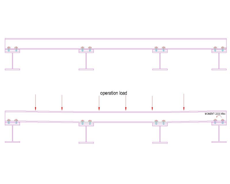
This skid is not anchored to concrete. It will be mounted to another steel frame. Hence the anchoring point is not rigid in Y(Vertical) Due to this when there is a operational load base beam member will subject to some deflection. which will create moment. In analysis it is not pinned connection. It is fixed but with vertical spring constants.

fdn-Model_a3kd6r.jpg
 
Eureka... It's a pin!

Can beam it's sitting on support a 2000kNm torsion? No I am guessing? Then it's behaviour is close to a simple support in reality.

Something is wrong with your support assumptions if you are getting any moment (as torsion) into the supporting beam. If you don't believe us actually model the 4 support beams and you will see some small torsion in the supporting beam even with a 'fixed' end connection between the frame and the supporting beams. You will not have a 2000kNm moment at the support location.
 
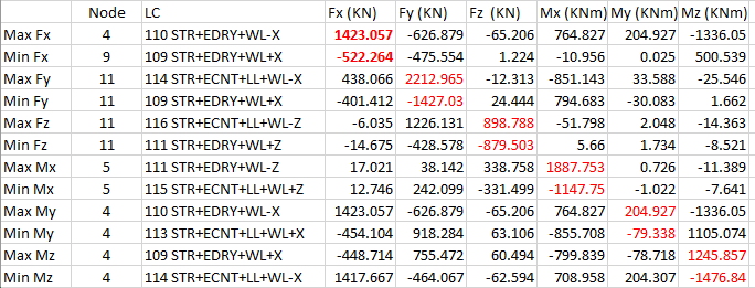
The heavy moment is due to the column, equipment & mainly wind load on a vertical vessel above the skid. The vessel height is more than 10m. it is in the corner of the skid. The exact moment is 1887 KNm.
 
Hi Agent666

The problem is that like me, according to the OP you don't understand the problem.
For example we started off with a sketch showing a column and a beam with an end moment which as suddenly transformed into a beam with 4 supports but we should have guessed this without the OP informing us.
Having asked what's creating the moment and where this does this force act we seem to get a fluid answer, on the 16th the 2000kNm was due to some equipment a and column resting on the beam and today we are told its created by wind loading on a vertical vessel above the skid but hey we should have guessed that from the information given, clearly our crystal balls are due for a service,

I doubt that the OP will accept that it is his lack of understanding and knowledge of how to ask a question is the real problem.

“Do not worry about your problems with mathematics, I assure you mine are far greater.” Albert Einstein
 
Anupriya123, is the moment actually the reaction? Or is it just the moment in the frame at the support.

If it is the reaction and you are getting a moment transferring to the supporting beam as a torsion, then something is wrong in your model. Please provide printouts of the moment, shear, reactions and deflections so we can understand your analysis you are relying on.
 
The drawing showing the location of those nodes on the model got dropped by the upload genie.
 
You appear to be fixing your frames for moment at all supports. This assumption is inconsistent with the detailing. Pin these supports, or explain why you think they have moment fixity at these locations?

I was really referring to providing the shear and moment diagrams, not just a list of numbers which we have no idea where they apply.
 
Or just design the bolts for 6000kN force if you don't think your support beams will rotate as per the graphic you provided.

 
This thread renews my thought that what goes on in the engineering world is scary as hell.......makes me wonder how things I walk by everyday were designed.
 
Status
Not open for further replies.

Part and Inventory Search

Sponsor