Eng-Tips is the largest engineering community on the Internet

Intelligent Work Forums for Engineering Professionals

Anchor bolt of deck railing check

Status
Not open for further replies.

Star.1

Structural
Feb 20, 2024
2
0
0
NP
For the check of railing post top mounted on deck, is the check of shear and tensile capacity of anchor bolts sufficient?
Considering the point load of 200lbf at top of rail, the 3/8” dia. anchor bolts are checked for shear and tensile capacity induced by moment due to that point load. For the shear capacity check, AISC table 7-1 and 7-2 values are used for bolt capacity. Will these two checks be sufficient? I have carried out the calculation as such:
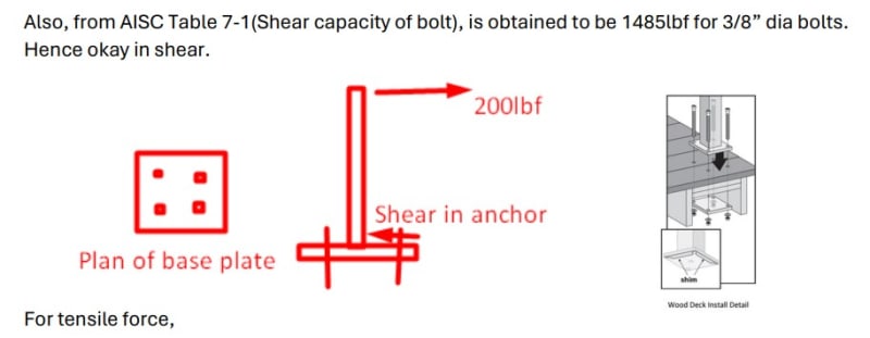
No. of bolts used in base plate=4
Shear load=200lbf
Shear load per bolt=200/4
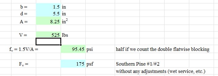
Shear capacity of bolt and blocking connection is checked for double shear plane load in AWC connection calculator. The capacity is 784lbf. Hence okay.
Also, from AISC Table 7-1(Shear capacity of bolt), is obtained to be 1485lbf for 3/8” dia bolts. Hence okay in shear.
For tensile force,
Moment (M)=200*42in (Height of rail=42in)
Tensile force on pair of bolt=(M/2)/LEVER ARM BETWEEN SCREWS
This force is checked with tensile capacity of bolt from AISC table 7-2.
Attachment includes the illustration.

 
 https://files.engineering.com/getfile.aspx?folder=afbf3f0b-caf2-46af-a692-271947c8ccfd&file=Deck_railing.pdf
Replies continue below

Recommended for you

I've only given this a cursory look over but:

1) In general, it looks as though you're on the right track.

2) I feel that this is a single shear condition rather than a double shear condition.

3) I'm not sure how accurate it is to say that the lever arm is the distance between bolts. The compression side bolt won't actually see any compression. That said, the lever arm is probably pretty close to that for this situation.

4) One might take a look at the connection between the blocking and the supporting framing for uplift forces. I imagine that shear gets dragged back into the deck pseudo diaphragm.

As you know, one can't be too much of a hardass about this stuff and expect a reasonable solution.
 
That flatwise blocking under it is going to rip out way faster than any connection to the railing. <<< CRITICAL

3) - you need a realistic force distribution here. This method isn't accurate. Unless you are presuming the plank offers no resistance.
 
I was gonna say the same thing as above about the double shear plane. I don’t think that’s accurate if I’m understanding the connection detail correctly.

I would probably base the lever arm on the distance from center of bolt on tension side to center of compression bearing area at the compression side, although going bolt to bolt is probably conservative, I would guess.

I recently took an in depth look at railing post connections, and it’s often challenging to get these to work by the book when looking at the full load path. The blocking and other nearby framing members get highly stressed and those connections are often overlooked.
 
To echo others, the blocking will be critical.

Bolt to bolt is rarely conservative on these. It will be bolt to the centroid of a triangular bearing stress distribution under the opposite side. The high end of the triangle will be set to the max bearing stress of the limiting material - in this case wood decking. It'll be a fairly straightforward system of equations resulting in a quadratic to be solved.

Check out AISC Design Guide 1 for a general overview of the procedure...just have to swap out for the appropriate stress limits and distributions.

 
Last time I looked (before the paywall) the Acceptance Criteria for guardrails required a substrate attachment, yet none of the ESRs actually showed the attachment or limit the substrates (concrete, steel, etc). You got the exposed to weather, the potential for dissimilar metals, and the physics of the base plate they give you are all major constraints. When you try to attach this into wood blocking, the end reactions are large and so are the shears in the wood pieces. They are very challenging and require a lot of attention, a lag screw will typically not do what you need it to do here, and it won't be installed correctly (two diameters of drilled holes last I checked). Lag screws are also galvanized, at best, last I checked, so it becomes the sacrificial anode if there's stainless steel plate or railing attached to it.

Loferski and Woeste had a good paper on the wood guardrail itself but for a plated bottom guardrail it's useful as a guide you can work from, not something directly workable. Other articles, Guertin, etc. in JLC go over attaching to blocking and other issues. The blocking is really difficult to get to work if it's taking the load.
 
OP, if you don't believe us on the blocking, take a look at some of Simpson's code-based design guides for their screw only approach. They use blocking to hold a 4x4 post in place with only their screws. Each post requires as many as 20 heavy duty structural screws to make the connection.

Simpson Deck Connection Guide Excerpt
 
phamEng, I use a rectangular stress distribution rather than triangular for bearing area with wood. I believe that’s what NDS 3.10.2 requires. I don’t think I’ve ever seen the triangular distribution in any reference documents, although I do see the logic.

lexpatrie, I think OP is using thru bolts, not lag screws.

Maybe I’ll run some calcs on this detail if I get a chance. I tend to think the decking/blocking will be the weak link.
 
Honestly, I would not even bother with a shear check on the bolt. There will be enough friction here from the compression side of the couple.
I typically turn down these jobs due to the difficulty in getting them to calc out.
 
Eng16080 said:
I believe that’s what NDS 3.10.2 requires.

Honestly, I've never noticed that line before. Or if I did, it didn't stick. The wording..."no allowance shall be made" makes it feel like there's some benefit you can gain from assuming there is a variable distribution. What that is, I don't know. But it does specifically say 'for bending members' so that sounds like it's referring to end bearing conditions for beams and not necessarily moment connections.

The variable distribution is real, and in this case would produce a worse effect as the lever arm between a rectangular distribution is longer than the triangular. That would underestimate the bolt force in the couple.
 
phamEng, Yeah I’ve always found the particular wording odd. I figured the rectangular distribution is some type of approximation. Logically, it seems that the reality would be a triangular distribution, at least assuming the base plate is very rigid.

In the case of end bearing of a bending member, especially if simply supported, I would certainly expect the true distribution to be triangular in that case.

I forget if the code commentary says anything about that. I don’t currently have it handy. Perhaps has something to do with the bearing stress being considered an average.
 
Yeah that specifically states at ends of bending members.... That seems to be more about allowing the stress to be spread across the full length of the bearing evenly. If you did account for the rotation of the joist, you'd likely see crushing on the front edge of the plate. Keep in mind plate crushing isn't quite failure. It just deflects down a bit and it's not even linear at 100% of the allowable. (More treatment of that in the Woodworks material by Thompson)

2018_NDS_3.10.2_scu3xq.jpg
 
I agree with lexpatrie in most cases - the 'failure' is more of a serviceability issue. It's not going to cause a collapse, but you can start getting unpleasant variations in floor levels and other similar situations that can cause cracking in finishes. The listed bearing stress limit is based on a certain amount of crushing. So even at 50% of the value, some 'crushing' is already taking place...just not enough to worry too much about.

In cases like this, though, where the crushable material is the contact surface for a cantilevered end plate moment connections...I treat crushing as a strength limit state.

And yes, given the drastic different in flexibility between the crushing of the wood and a metal plate (unlike concrete vs reasonably proportioned steel at yield/crushing where a rectangular block makes some sense), my preference is for a triangular distribution.
 
phamENG said:
The listed bearing stress limit is based on a certain amount of crushing. So even at 50% of the value, some 'crushing' is already taking place...just not enough to worry too much about.
Agreed. Per NDS 4.2.6, for sawn lumber, the reference design values are based on a steel plate crushing the wood by 0.04".
 
Not sure if OP is still around, but in any case I took a little bit of a closer look at this detail for my own curiosity, and overall I don't think it's that bad. This is assuming the lever arm distance at the base plate isn't too small (which is difficult to assess without dimensions).

The connection between the double blocking and the joist/rim board should be doable. I get a shear force at the ends of the blocking of roughly 42" x 200 lb / 16" = 525 lb, which is based on the joist and rim board being spaced at 16". This force can be resisted with half a dozen or so nails/wood screws. This also doesn't account for the extra resistance from the deck boards.

In some ways I like this detail better than the typical side mounted railing post.
 
I wasn't advocating ignoring crushing in this situation, I was meaning in general, it's not all that critical, plus, the way we check those items isn't very realistic in the first place and when failure is "predicted" it may not cause a problem, i.e. finishes are installed late versus at least some of the dead load. A more realistic check would involve loads in place before the finishes are placed, in a plausible sense, you can't conceal plumbing or fire sprinklers before there's an inspection, so the ceiling has to go on later, same with the wall, typically. You might even get nonlinear crushing as it goes past the .73 Fcperp somewhere in that loading sequence. You get larger deflections when there's not a metal plate bearing, that's covered in Thompson, Five-Story Wood-Frame Structure over Podium Slab, Thompson, P.E., S.E., Woodworks, date not exactly known, last updated circa 2017, see page 47 for a very good treatment of the subject.

I might as well add this image so folks don't have to click through the original post so it's easier to participate and visualize.
Excerpt_-_Guardrail_figures_jafcon.jpg

(that's not the entire PDF).

I this situation crushing could be perhaps bypassed is a fair description of it, if there is another valid load path (i.e. the fasteners in compression), then crushing of the wood is undesirable but would not lead to catastrophic failure. But the metal plates would suggest a linear / triangular stress distribution as the wood would be very soft compared to the metal plates. That bit about a rectangular stress block is for the end of the member, i.e. a joist bearing on a 2x plate is treated as a uniformly distributed load. It's not saying you have to use it everywhere, and even if it did, that's contrary to the generally accepted principles of mechanics and you as a P.E. should ignore it.

Side note: I think I misread something, I thought Guertin was a P.E. out East, but the profile doesn't say that. Some of the details here - Code Compliant Guardrail posts look like they don't have a fully worked through load path. That isn't a great title for that article as it's not a sealed design from an engineer and there's no Chapter 17 testing, either. Loferski and Woeste were using testing as a lot of their work does (the 2x2 ledger strip, guardrails, etc). NADRA should really just pay an engineer to produce these designs and be done with it. Then we can all start figuring out how to ventilate a balcony.

When it comes to this particular design, that shear load through the flatwise blocking doesn't look viable to me, end nails into the blocking, for one, the shear in the blocking, and the connection hardware. The depth is 1.5" for fv = 1.5V/A. There isn't any support under it so you can't reduce the check to d from the face, and in the simplified sense, that's a square shear diagram due to what is pretty much a point moment. Maybe it works on the math, depending on how much wet service you want to throw at it, and the connections also have that wet service to contend with. I don't see a mechanical connection (screws, nails) between the flatwise blocking and the joist that's going to take that force. I didn't like the shear in the blocking but that's maybe workable.

Just presuming the 525 lbs is correct...

Blocking_shear_hc31ze.jpg


Not sure how I feel about nails/screws here when we are dealing with wet service and durability. They aren't all that exposed to view for a two year or five year inspection, either. Nailing and screwing in to the end grain also seems like a good way to split the wood anyhow.
 
lexpatrie, thanks for posting OPs image. I hate having to click the link, then download and open the PDF every time.

lexpatrie said:
You get larger deflections when there's not a metal plate bearing, that's covered in Thompson...
This is also covered in NDS, Commentary Section C4.2.6: "For the same stress, deformation of a joint consisting consisting of two wood members both loaded perp. to grain will be approx. 2.5 times that of a metal to wood joint." I agree that the 0.04" crushing limit for metal on a 2x piece of lumber used to establish the Fc_perp values is probably highly variable. If the wood is wet or is thicker than 2x, I would expect more crushing/deformation.

lexpatrie said:
That bit about a rectangular stress block is for the end of the member, i.e. a joist bearing on a 2x plate is treated as a uniformly distributed load. It's not saying you have to use it everywhere, and even if it did, that's contrary to the generally accepted principles of mechanics and you as a P.E. should ignore it.
Fair enough, although I would contend that if a non-uniform stress distribution is allowed in this particular case, why wouldn't it be allowed in another. I've also never seen a triangular stress distribution used in a wood design example nor mentioned in any of the reference material that I have.

lexpatrie said:
Some of the details here - Code Compliant Guardrail posts look like they don't have a fully worked through load path.
I did some recent research on this subject in the interest of revising my deck railing post details. I was unable to find a fully worked design example anywhere. I suspect this is partially due to it being very difficult to get it to work. In my own calculations, I had difficulty arriving at reasonable solutions. I was also assuming a uniform bearing stress distribution. With a triangular distribution instead, seemingly it would be even more challenging.

lexpatrie said:
When it comes to this particular design, that shear load through the flatwise blocking doesn't look viable to me, end nails into the blocking, for one, the shear in the blocking, and the connection hardware.
I don't love this connection, although, by the book it should work. I ran some rough numbers which did account for a wet surface factor of CM=0.7 and an end grain factor of Ceg=0.67. Using a load duration factor of CD=1.6 somewhat offsets these deductions. I also am aware that using CD=1.6 is debatable. Still, using CD=1.0 instead would, I think, still result in a connection working, just with more nails/screws. It's a good point concerning the long-term condition of this connection after the wood has dried out. Perhaps something live a (galv.) metal connector angle would be better. Wood screws into the deck boards with decent pullout capacity should also help matters.


The DCA6 guide doesn't, for example, show a calculation for how the hold-down force is determined. I understand that it's based on testing, but it would be nice to see how one might go about working out a solution without testing. Also, using CD=1.6 is questionable. In that document they seem to arbitrarily choose that value because the load rating for most hold-down connectors (which are primarily intended for wind loads) are based on it.
 
Eng16080 - I agree. But then the IRC doesn't do calculations for very much of anything. It's prescriptive.

As for the assembly and 'calcing it out'...the conclusion of Loferski, Albright, and Woeste's paper isn't terrible encouraging.

Tested Guardrail Post Connections for Residential Decks; Loferski said:
"A load tested post-to-deck-connection design is very difficult to achieve."
"A commercially available connector...post-to-deck assembly was evaluated, and it passed a load test based on building code provisions for a "tested assembly".

So there are ways to 'fudge' the numbers and make it work. But I agree, 1.6 is not appropriate. C[sub]D[/sub] is based on cumulative loading at that level over service life, not per occurrence. And if you consider a 250lb person leaning against a rail with there legs at a nice, stable, 70 degrees from horizontal, you come really close to 50lbs/ft if they're standing close enough. I realize residential doesn't have to play by that rule, but considering you can put residential guardrails 8ft on center if you want to, the chances of getting to 200lbs are better in residential (especially short term rentals on the beach!).
 
Status
Not open for further replies.
Back
Top