Continue to Site

Eng-Tips is the largest engineering community on the Internet

Intelligent Work Forums for Engineering Professionals

  • Congratulations KootK on being selected by the Eng-Tips community for having the most helpful posts in the forums last week. Way to Go!

Anchor bolt of deck railing check

Status
Not open for further replies.

Star.1

Structural
Feb 20, 2024
2
For the check of railing post top mounted on deck, is the check of shear and tensile capacity of anchor bolts sufficient?
Considering the point load of 200lbf at top of rail, the 3/8” dia. anchor bolts are checked for shear and tensile capacity induced by moment due to that point load. For the shear capacity check, AISC table 7-1 and 7-2 values are used for bolt capacity. Will these two checks be sufficient? I have carried out the calculation as such:
No. of bolts used in base plate=4
Shear load=200lbf
Shear load per bolt=200/4
Shear capacity of bolt and blocking connection is checked for double shear plane load in AWC connection calculator. The capacity is 784lbf. Hence okay.
Also, from AISC Table 7-1(Shear capacity of bolt), is obtained to be 1485lbf for 3/8” dia bolts. Hence okay in shear.
For tensile force,
Moment (M)=200*42in (Height of rail=42in)
Tensile force on pair of bolt=(M/2)/LEVER ARM BETWEEN SCREWS
This force is checked with tensile capacity of bolt from AISC table 7-2.
Attachment includes the illustration.

 
 https://files.engineering.com/getfile.aspx?folder=afbf3f0b-caf2-46af-a692-271947c8ccfd&file=Deck_railing.pdf
Replies continue below

Recommended for you

phamENG, Yeah, don't even get me started on this. I naively figured it wouldn't be that difficult to design a damn railing post based on engineering principles. I was wrong. Once again, I paid the price for looking a little too close. I could probably design a house in less time than I've spent on this.

Concerning the railing post detail, my key take-ways are:
[ol 1]
[li]What CD value should be used? 1.6, 1.0, or something in between? I ultimately decided to try to get a connection to work with CD=1.0. In most cases, this only worked if the deck framing was 2x10/2x12. Since the Simpson hold-down connectors are based on CD=1.6, their rated loads needed to be adjusted down. Also, with CD=1.0, the (normal sized) 4x4 railing post is marginal at a 36" railing height. At 42", a 4x6 is needed.[/li]
[li]Should the 200 lb concentrated load be applied in any direction (as required by code) or just in the outward direction? I might be the only engineer in my geographic region to even consider a load not only applied outward. I was able to get a detail to work with both inward and outward loads, using two hold-down connectors. The inward load is probably less likely to occur and also less of a risk should the railing fail. Where this type of loading could realistically occur (which I've observed) is in supporting a hammock.[/li]
[li]Since the moment arm calculation is critical in determining the compression and tension (hold-down) forces, determining the centroid of the bearing area and the bearing distribution is really important. I assumed a uniform bearing stress, which is non-conservative versus a triangular distribution. Even with a triangular distribution, it seems that the bearing stress isn't linear with respect to strain. Also, the bearing stress values per NDS are based on a somewhat arbitrary deformation limit of 0.04" (based on a steel plate bearing on wood). Perhaps using different values is therefore warranted.
A better analysis method than the one I used would account for the total deformation limit at the top of the post, based on some kind of relationship between the bearing stress and bearing deformation.[/li]
[/ol]
 
Keep in mind those Loferski and Woeste articles et. seq. all came out before the newer hardware that was developed after these articles appeared, circa 2006.

Analytically challenging, yes.

Testing leaves the load in place for 24 hours, so that's a potential source for an alternative CD.

Literal code (probably IBC versus IRC) says any direction, so there's the transverse direction too. The one that feels the most critical is the plunge into free space perpendicular to the edge. You'd have to point at the various prescriptive designs and claim they didn't do the inward load case, either, as a kind of backup defense. I think falling onto the deck is far less dangerous than falling off it..... but the literal code doesn't acknowledge that. I'm not sure there's a history of failures in that direction, however, or of injuries. If they were minor injuries though, they might go unreported/untreated.

I'm used to seeing triangular stress distribution used for base plate compression tips (steel to concrete, I admit), so I just automatically went there, the plate should be stiff enough to force this, although the non-linear nature of the crushing is an interesting point. And come to think of it, I don't think I've seen a calculation in any wood textbooks that use a triangular stress distribution. Like I said, if you could get a compression load out of the fasteners on that side that's perhaps a bypass, although the wood may still crush. (Let's ignore hollow plastic composite lumber for a moment)

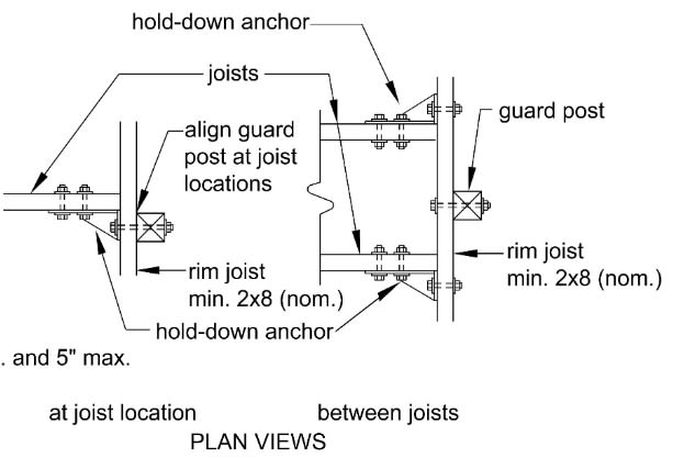
I didn't know the guardrails Guertin presented were from the DCA. DCA is residential, of course, so 36" high probably. The ones (or at least the one that springs to mind) that make me wonder are the ones where they attach the post to the rim board between two joists and put the hold-downs on the joists to the rim.

Funky_guardrail_detail_c3l3zu.jpg


That's probably not a comprehensive response to everybody, but it's a start.

I think there's room for discussion on a duration of load that's above 100%. If it fails, however, you'll have to lean on "standard of care" in your local engineering community, though. 1.6 would have to be the maximum. Anywhere from 1.6 to 1.0 is possible to justify, and 1.0 is okay without question. I point at the 24 hour not only as it's the testing duration of load in Chapter 17, but also in case somebody stacks (construction) material against them, say during a fire repair of the interior, it could easily be there for a day. If the DCA designs don't calculate or test out, that'd be another prong in a defense.
 
It's somewhat funny to see the various "Code-Compliant" railing post articles that disregard any loads other than in the outward direction. At least the Loferski and Woeste article acknowledges that.

In the commonly used detail above with the post "between joists," I found it impossible to get that connection to work without using blocking very close to the post. Maybe if you made a sort of built-up "C" shaped beam using a deck board above and another board below, that might work in terms of resisting the bending/torsion. (Although nobody does that.)

I recently constructed a similar detail while building a ramp, and I initially didn't add any blocking. I was surprised how much the whole thing flexed while pushing on it (with maybe only 50 lbs force) at the top.
 
Ah, that one. It puts the rim joist in torsion. I know there are some documents out there that put allowable torsion for rectangular wood beams at 1/3 of F[sub]v[/sub]', but I don't have anything handy to point to. I also haven't checked this particular issue. I'm guessing it just 'worked' in the tests.

Regarding load duration, you're probably right. The ICC test procedure requires a factor of safety of 2.5 applied to the design load, and the load duration factor for 24 hours is a little over 1.3...so you could extrapolate a factor of safety on the design load of 1.92 for duration factor of 1.0. Considering wood has the safety factor applied to the capacity side, it becomes a non issue. Though...it's a non issue anyway because it's a tested assembly, not a designed assembly.

The direction of load is one of those 'whistle and walk by looking other way' things, more often than not. Which is...unpleasant. I believe some of our Canadian brethren mentioned there was consideration of a change in their code to 200lbs out and 50 in any other direction to more adequately represent the risk and likelihood of loading. If it's true, hopefully ASCE 7 and ICC will follow suit.

 
I believe the Timber Construction Manual by AITC provides some guidance on torsion, although I'm not familiar with it. I looked at each of the two point loads on the rim board being resisted by half the depth of the rim board, and it wasn't even close to working in bending. Of course, this isn't totally accurate, as it neglects torsion.
 
Status
Not open for further replies.

Part and Inventory Search

Sponsor