Continue to Site

Eng-Tips is the largest engineering community on the Internet

Intelligent Work Forums for Engineering Professionals

  • Congratulations IDS on being selected by the Eng-Tips community for having the most helpful posts in the forums last week. Way to Go!

Anchor Bolt / Pedestal / Foundation Connection

Status
Not open for further replies.

azcats

Structural
Oct 17, 1999
688
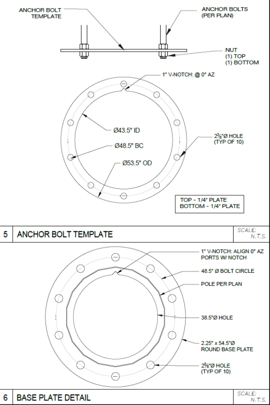
Looking for some input on design/evaluation of the situation below. Existing structure that my company owns which was engineered and recently built by others. I'm evaluating some changes to the loading. Foundation for a telecom tower with large (2400 ft-kips factored) overturning moments and fairly low (30 kips) axial loads. Anchor bolts are 18J bars that are threaded each end. While deformed, they're nowhere near enough embed to be developed in tension.

The pedestal was designed flexurally and the anchor bolt embed was evaluated to develop the pedestal reinforcing above the concrete breakout failure plane. This is how I typically see it for drilled pier foundations and it appears they applied the same logic here.

My issue is that the reinforcing is not developed below the anchor bolt concrete breakout failure plane. So I got into checking the concrete breakout strength in tension and my approach is leading to failure.

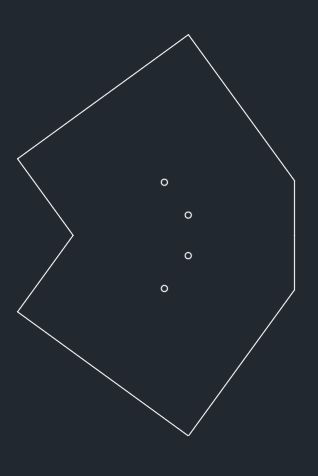
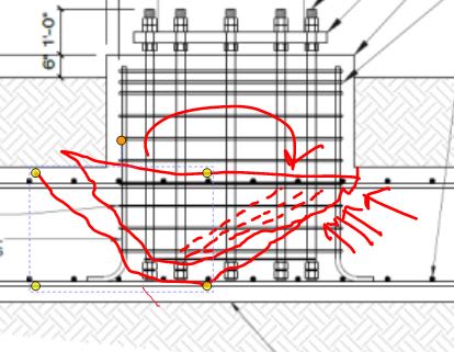
I analyzed the bolts about the Y axis in the pattern sketch below. So there are 4 bolts in tension, 2 on the neutral axis and 4 in compression (no grout). The axial loads skew towards compression by a few kips. Total tension in those 4 bolts was approximately 700 kips. With an heff of ~26" (using the 3' deep footing only), Anc for my odd 4 bolt pattern (shape is below) was 9573 and I get an phi-Ncbg of around 247 kips (way off).

So I guess my questions are these:
1. Should I have completely neglected the pedestal vertical reinforcing in my tension capacity? Can it assist at all?
2. My failure plane passes thru the pedestal which was cast integrally with the foundation. On that side it would pass thru reinforcing that is developed below. Any reasonable manner to consider that reinforcing?
3. Is it appropriate that I've completely neglected the anchor bolt deformations?
4. I did not consider the template embedded in the concrete to add to the Anc as it was only 1/4" thick. Too conservative? That would also increase my heff by a couple inches.
5. Any flaws in my general approach to this evaluation?

Input or questions welcome.
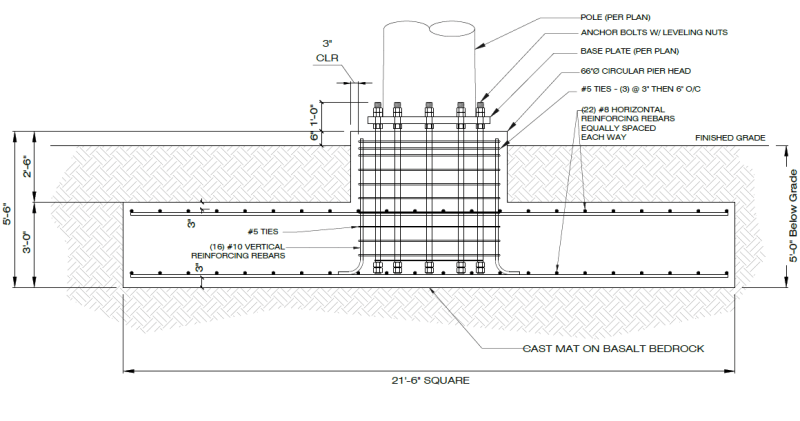
Ftg_Elev_pl19wg.png


AB_Pattern_y8as2f.png


Anc_qha2ug.png
 
Replies continue below

Recommended for you

1. I would account for the pedestal vertical rebar.
2. I'm not sure of the wording of this point. Are you asking if the top mat of steel in the footing passes through the failure plane?
3. No comment.
4. I would account for the template even if it is a slight increase.
5. Have you considered the forces in a simplified manner or the actual distribution on a round column (see Daniel Horn's document).

There's lots of flexure in this foundation. I'm surprised to see how shallow the design is with respect to the length of the anchor bolts.


...but I can't recall if I have ever solved that problem yet.
 
Per this thread507-456306 (see WARose's posts), those embeds are extremely thin, and I wouldn't account for it.

I feel the same as skeletron, the whole thing looks mis-proportioned.

From my understanding of appendix D, you can only bypass the failure cone if you pass it to tension rebar, but the rebar needs to be developed on both sides of the failure plane.

Is it possible to contact the other engineer and find out what load path they were expecting?
 
OP said:
1. Should I have completely neglected the pedestal vertical reinforcing in my tension capacity? Can it assist at all?

I would have neglected it too. In that configuration, it would only add a bit of un -uantifiable dowel action to help out.

OP said:
2. My failure plane passes thru the pedestal which was cast integrally with the foundation. On that side it would pass thru reinforcing that is developed below. Any reasonable manner to consider that reinforcing?

I'm not seeing this. Can you elaborate?

OP said:
3. Is it appropriate that I've completely neglected the anchor bolt deformations?

You mean for bond? If so, then yes. I'd think that your bolt nuts are fulling grabbing the failure frustum and the rod development would not add to that.

3 said:
4. I did not consider the template embedded in the concrete to add to the Anc as it was only 1/4" thick. Too conservative? That would also increase my heff by a couple inches.

Agreed. Way too thin other than to possibly consider the template as washer locally with projection equal to thickness.

OP said:
5. Any flaws in my general approach to this evaluation?

I think that you're on the right path in general.

c01_btn1yk.jpg


HELP! I'd like your help with a thread that I was forced to move to the business issues section where it will surely be seen by next to nobody that matters to me:
 
There's a procedure for estimating the benefit of a model like this but the benefit would be nowhere close to being on the order of the improvement that you need here.

c01_ylypzx.jpg


HELP! I'd like your help with a thread that I was forced to move to the business issues section where it will surely be seen by next to nobody that matters to me:
 
For a moment applied on a circular pattern, I've treated that as an equivalent vertical load, setting P=2M/R,then check shear in the slab as for punching shear.
That is very nearly the situation KootK is showing in his next-to-last picture up there.
 
I don't think the designer would go to the trouble of procuring 18J material if they weren't trying to transfer tension into the pier through bond. Otherwise they would just use regular anchor bolts, right? In reality the anchors probably behave like headed rebar, with some load shedding off via bond down the length of the shaft and some being resisted by bearing at the nuts. My guess is the nuts are only there to attach the template and aren't considered for strength at all. I doubt there's enough embedment depth to to develop the yield strength of those jumbo bars, but maybe they only needed partial development.
 
bones206 said:
I don't think the designer would go to the trouble of procuring 18J material if they weren't trying to transfer tension into the pier through bond.

I'm sure you're right but, then, I doubt that it matters in the final analysis. Even if all of the tension were transferred to the pier cage, the concrete breakout failure mode would remain effectively the same. Just a few inches wider.

In my opinion, the biggest faux pas in structural engineering these days is people confusing development with anchorage. And I suspect this is what happened with the original design here. "Breakout doesn't work? No worries, I'll just replace the anchor bolts with threaded bar". I know... I'm a broken record on this particular subject. I'm starting to bore myself.

HELP! I'd like your help with a thread that I was forced to move to the business issues section where it will surely be seen by next to nobody that matters to me:
 
The more I think about it, I'm probably wrong.. I think it's more likely that they considered the breakout failure, but just whiffed on the development of the #10 bars (on the hooked end). But then why go with deformed bar anchors? Hopefully some of the transmission folks on here will chime in and illuminate us.
 
Thank you for all the input.

skeletron said:
2. I'm not sure of the wording of this point. Are you asking if the top mat of steel in the footing passes through the failure plane?
KootK said:
I'm not seeing this. Can you elaborate?

My thought was that the breakout failure plane on the pedestal side (left side of the black snapshot in OP) would continue vertically into the pedestal and either engage the pedestal verts on that side or increase my effective embed. Grasping at straws with this one and certainly wouldn't account for the difference.

skeletron said:
5. Have you considered the forces in a simplified manner or the actual distribution on a round column (see Daniel Horn's document).

This was an elastic analysis with the approach recommended in the Horn document for an un-grouted baseplate.

winelandv said:
Is it possible to contact the other engineer and find out what load path they were expecting?

We'll get there soon enough I imagine.

bones206 said:
I don't think the designer would go to the trouble of procuring 18J material if they weren't trying to transfer tension into the pier through bond. Otherwise they would just use regular anchor bolts, right? In reality the anchors probably behave like headed rebar, with some load shedding off via bond down the length of the shaft and some being resisted by bearing at the nuts. My guess is the nuts are only there to attach the template and aren't considered for strength at all. I doubt there's enough embedment depth to to develop the yield strength of those jumbo bars, but maybe they only needed partial development.

bones206 said:
The more I think about it, I'm probably wrong.. I think it's more likely that they considered the breakout failure, but just whiffed on the development of the #10 bars (on the hooked end). But then why go with deformed bar anchors? Hopefully some of the transmission folks on here will chime in and illuminate us.

18J anchor bolts are still common in this industry and most of the pole suppliers keep them in stock. They have yet to make the transition to F1554 material. A couple benefits are that AB twisting in the concrete isn't an issue and you can use the deformed bar for compression development in cases like this. From a tension view, the deformations are neglected.

KootK said:
I'm sure you're right but, then, I doubt that it matters in the final analysis. Even if all of the tension were transferred to the pier cage, the concrete breakout failure mode would remain effectively the same. Just a few inches wider.

I'm not sure I'm seeing this. This situation was run thru two foundation analysis packages and showed no failures in punching shear or in the pedestal vert development. I'll dig into those items in more detail to educate myself. Maybe I'm being caught in your development/anchorage trap. My initial thought was that they should have made the pedestal taller where the breakout failure plane would have had bar development both above and below. But you're saying that wouldn't work.

Could the disconnect be the fact that my bolt forces are T&C about a neutral axis where the pedestal design engages more verts with the compression block over at one edge? I guess theoretically, I could decrease my tension forces by designing this as a grouted connection, no? (it's not currently grouted.) But that still doesn't get the verts developed below the plane.

 
I think you would need at least 13 #10 bars to take the 700 kips off those 4 anchors.

As = 1.27 in2
Fy = 60 ksi
Phi = 0.75

#10 Strength = phi*As*Fy = 57.15 kips
700/57.15 = 12.25 bars —> 13 bars req’d minimum

But those 13 bars would have to be within a certain distance of those 4 anchors to be effective. And again, developed above and below the assumed breakout plane.

I wonder if the original designer neglected the downward axial load, so the software calculated a neutral axis offset from the anchor group centroid, which increases the number of tension anchors to 6 (or more?), increases Anc, and increases the number of #10 bars credited as anchor reinforcement.
 
bones206 said:
But those 13 bars would have to be within a certain distance of those 4 anchors to be effective.

So, if that pedestal had the flexural capacity to resist the moment with the (16) verts, and those bars are developed both above and below the breakout plane, would the anchor to pedestal connection be adequate? Or do you contend that each group of (4) anchors would still need the (13) bars within the effective area of those anchors? I'm not sure about this. That tension doesn't exist in a vacuum but as a part of the imposed moment. But I see where you're coming from.

bones206 said:
And again, developed above and below the assumed breakout plane.

I think we all agree that the design presented in the OP is not good. My thought is the designer didn't even consider the anchorage to the slab. They did check the development in the pedestal above the failure plane but not below. The pedestal itself is structurally sufficient for the loads. But the foundation system is modeled with the loads at the top of the pedestal and the software used does not consider the anchorage. I'm guessing (?) that the software calls it good if the pedestal bars are developed into the footing, but there is contention here about the adequacy of that assumption.

I've spent part of the last couple days angry with KootK for the results of my "site:eng-tips.com KootK anchorage development" search. All I wanted yesterday afternoon was a nice nap. But no, I'm laying there visualizing anchorage details and strut-n-tie models. Thankfully my ACI is at work so I wasn't able to crack that open. I'm admittedly weak in concrete design but looking forward to figuring all this out.

Thanks again to everyone so far for their input.


I think the only vertical bars that can be credited as anchor reinforcement are those which cross the assumed breakout plane of those 4 tension anchors. The moment resistance of the pier itself is based on a full plane section, with stress distribution based on elastic theory. But the breakout resistance of the anchors is based on an assumed pyramid-ish chunk of concrete trying to pop out and only being held together by whatever rebar is crossing that crack plane.

ACI 318 only considers reinforcement to be effective within 0.5hef of the anchor, but that doesn't really come into play with such a deep embedment in this case. So just be consistent with your assumed failure plane that you sketched out in your first post. Overlay that with the vertical rebar pattern and however many bars fall within the perimeter could be counted as anchor reinforcement. Bars outside that perimeter might be part of the pier's overall flexural resistance, but I don't see how they can be holding that anchor breakout plane together if they don't cross it.

I almost think this design would have been better off with anchors 2 ft shorter so the #10's had a chance to develop on the hooked end. But maybe that was the anchor length they keep in stock and they could't make the foundation deeper due to the shallow bedrock.

azcats said:
All I wanted yesterday afternoon was a nice nap. But no, I'm laying there visualizing anchorage details and strut-n-tie models.

why engineers will never make it onto a corona commercial...
 
And now I've read the Widianto document and don't know what I believe anymore.
 
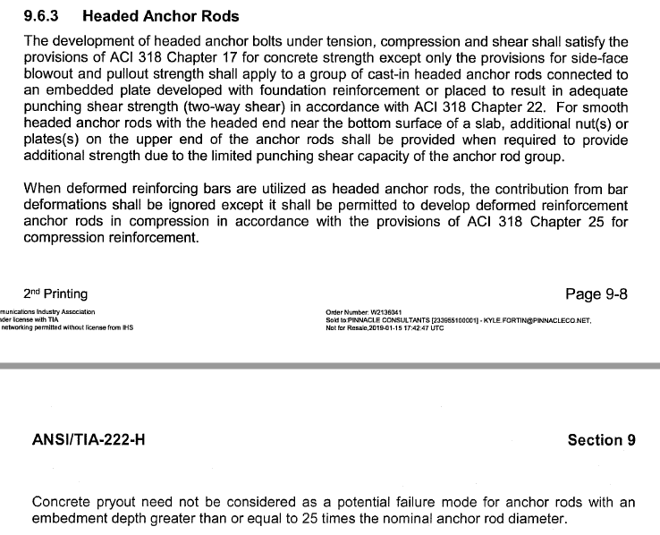
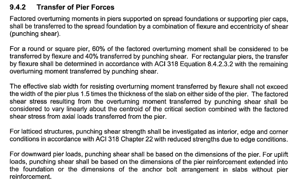
Below is a snip of a section from the TIA tower code which governs the design of this tower. It appears they allow the breakout to be neglected if the anchors are connected to a plate 'developed with foundation reinforcement.' This would be why the standard check in this industry seems to be the development of reinforcement. Again, unfortunately, in this case it is not developed below.

TIA_222-H_9.6.3_mx7po5.png


I also checked the anchor pullout neglecting the embed plate and it was 57% over-stressed. If I wanted to use some of that 1/4" plate, would it be possible? Thickness of the plate(?) - that's what 17.4.2.8 allows? Or is that far enough away from the bearing surface of the nut above that it's a no go? A calc using bearing of 8*f'c as a pressure yielded a length of only .187" before reaching the plastic moment. Hard to say the 1/4" plate would be effective at all. I also read the Grilli & Kanviinde report and the plates they used were >2x thicker than the anchors. I'm digging thru some old designs now and I'm not finding where anyone checks the anchor pullout. And I don't see how it works with these thin plates.
 
Sounds like the code give a choice between developing the anchors with vertical rebar OR checking punching shear of the anchor group. Maybe they went with the punching shear option. I’ve never heard of that being allowed as an alternative to the Chapter 17 requirements. Not even sure how you calculate that and why it would absolve the breakout failure mode.
 
Here's another section from the tower code.

TIA_222-H_9.4.2_os7wme.png


In my reading the last couple of days, there's an argument that anchorage force is similar in mechanism to punching shear. But it's not similar in calculation with anchorage being more conservative. . The Grilli & Kanvinde report discusses this a bit along with a third method.
 
Checking the footing for punching shear from the pier forces is a standard part of footing design. But the forces first have to transfer from the anchors into the pier, and that load transfer path seems to be deficient due to the lack of breakout capacity or properly developed anchor reinforcement. Even if the numbers work for punching shear, the anchors will fail in breakout before the punching shear failure can occur. It seems like they probably checked the anchor steel capacity and checked the pier capacity, but overlooked the transfer of load from the anchors to the pier.
 
There is an inherent difference in capacities between punching shear and anchorage. There have been some discussions on this forum before. My brief summary:
1) Anchorage calculations are based on un-reinforced concrete. By this I mean the testing that was done that forms the basis of the anchorage formulas was all done on un-reinforced concrete.
2) Punching shear calculations are based on reinforced concrete. Any testing that was done was based on reinforced concrete.
3) The anchorage calculations, in my opinion, are likely overly conservative.

I've heard of other engineering who will (for walls) merely extend the anchors through to the other side of the wall to a plate. Then they do punching shear calculations on the plate.

Someone (can't remember who) suggested to me that we should be able to do similar things with a mat / slab. Not extend the anchors through, but put a plate at the bottom of the anchors, and use a reduced thickness for the punching shear calcs. The main problem I see with this method is that you have a construction issue getting the concrete to flow below the plate.
 
Do we think that the presence of the 1/4" ring changes the governing failure mode from anchor group breakout to punching shear?

In my mind it does not. I still see a breakout cone originating from the nuts on the tension anchors. I can see the punching shear failure as a "global" failure mode once the mass of the pier concrete has engaged the overturning moment. But to get there, the tension first has to get distributed into the concrete mass from the anchor heads, which could result local breakout failure mode if not properly detailed.
 
Status
Not open for further replies.

Part and Inventory Search

Sponsor