Continue to Site

Eng-Tips is the largest engineering community on the Internet

Intelligent Work Forums for Engineering Professionals

  • Congratulations IDS on being selected by the Eng-Tips community for having the most helpful posts in the forums last week. Way to Go!

Anchor Bolt / Pedestal / Foundation Connection

Status
Not open for further replies.

azcats

Structural
Oct 17, 1999
688
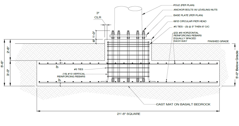
Looking for some input on design/evaluation of the situation below. Existing structure that my company owns which was engineered and recently built by others. I'm evaluating some changes to the loading. Foundation for a telecom tower with large (2400 ft-kips factored) overturning moments and fairly low (30 kips) axial loads. Anchor bolts are 18J bars that are threaded each end. While deformed, they're nowhere near enough embed to be developed in tension.

The pedestal was designed flexurally and the anchor bolt embed was evaluated to develop the pedestal reinforcing above the concrete breakout failure plane. This is how I typically see it for drilled pier foundations and it appears they applied the same logic here.

My issue is that the reinforcing is not developed below the anchor bolt concrete breakout failure plane. So I got into checking the concrete breakout strength in tension and my approach is leading to failure.

I analyzed the bolts about the Y axis in the pattern sketch below. So there are 4 bolts in tension, 2 on the neutral axis and 4 in compression (no grout). The axial loads skew towards compression by a few kips. Total tension in those 4 bolts was approximately 700 kips. With an heff of ~26" (using the 3' deep footing only), Anc for my odd 4 bolt pattern (shape is below) was 9573 and I get an phi-Ncbg of around 247 kips (way off).

So I guess my questions are these:
1. Should I have completely neglected the pedestal vertical reinforcing in my tension capacity? Can it assist at all?
2. My failure plane passes thru the pedestal which was cast integrally with the foundation. On that side it would pass thru reinforcing that is developed below. Any reasonable manner to consider that reinforcing?
3. Is it appropriate that I've completely neglected the anchor bolt deformations?
4. I did not consider the template embedded in the concrete to add to the Anc as it was only 1/4" thick. Too conservative? That would also increase my heff by a couple inches.
5. Any flaws in my general approach to this evaluation?

Input or questions welcome.
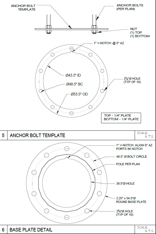
Ftg_Elev_pl19wg.png


AB_Pattern_y8as2f.png


Anc_qha2ug.png
 
Replies continue below

Recommended for you

Bones -

Good question. I don't know. What if the anchor rods were through rods and the plate was on the far side of the slab? I'd argue in that case that it would then be a punching shear situation. Though I'd check nut area + 1/4 spread all around for a crushing / bearing failure.

If the plate were under the bottom slab reinforcing I would have no problem doing it for this case. But, with it above the reinforcing.... I just don't know. If it were close to working with the rods alone, then I might use this concept to justify a slight overstress on anchorage calcs. But, if it's really far off then I don't think I'd be comfortable with it. I know the real capacity would be somewhere between the two methods. But, how far? I just don't know.
 
Given that the embedment is 3'ish and that the anchors are about 15" apart, I would suspect that you'd wind up ripping a mores or less monolithic chunk of the footing out encompassing several anchors. A failure mode involving a bunch of saw toothing in the failure frustum between anchors would probably develop more strength than the basic frustum failure mode. Of course, this is just more stuff that is very difficult to prove with any rigor.

HELP! I'd like your help with a thread that I was forced to move to the business issues section where it will surely be seen by next to nobody that matters to me:
 
I've been going thru some other existing designs by several engineering firms.

Is it inappropriate to post snapshots of other peoples' work here if all identifying info is removed?

I've got one that has a 2' x 24' square mat with a 84" x 5'-6" tall pedestal. If you though the OP design looked odd...
 
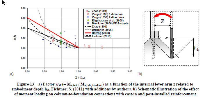
There are a bunch of different ways proposed to account for the effect KootK sketched. I have a handy graph showing the different methodologies and the resulting breakout strength modification. I'd suggest reading a couple of papers though if you plan to use it in a critical situation.

modification_for_breakout_strength_uuo9ft.png


This is from "Bridging the gap between design provisions for connections using anchorage or strut- and tie models" by Eligehausen et al.
 
azcats said:
I've spent part of the last couple days angry with KootK for the results of my "site:eng-tips.com KootK anchorage development" search.

The thread that you'd be looking for is this one: Link. Pretty much KootK vs the world there. And that highlights an important point about what I'm about to say. You will find many that disagree with me on this. Many talented engineers on this forum disagree. And much of what you will see in print will passively imply disagreement with my views. So weigh those things as you see fit. In my opinion, this is just more evidence that the misunderstanding that I feel pervades our community is, indeed, utterly prevalent.

Interestingly, THLS' reference is the first thing that I've seen in print that seems to support my hypothesis somewhat. I'd give him a constellation full of stars for that except that I don't feel that it's appropriate to issue stars to folks who simply help to reinforce your pre-existing opinions. TLHS will just have to feel my radar love from afar.

So... without further adieu:

1) People seem to think that a developed bar is an anchored bar, always and forever. If you examine the testing that informs bar development, it will become apparent that this is not the case. Development precludes but two kinds of "falure". The first is yanking the bar right out of the cylindrical slot into which it was cast (basically old school bond stress). The second is excessive slip prior to bar yield. Neither of these checks tells us whether or not a bar that remains in it's cylindrical slot will be prevented from pulling out of the global concrete mass, taking a chunk of concrete along with it. This latter failure mode is the stuff of AppD/CCD... the difference between anchorage and development. Thinking in terms of Venn diagrams:

a) All anchored bars must be developed but;

b) Not all developed bars are anchored.

2) It is true that, with infinite concrete masses, smaller bar sizes, and generous bar spacings, most bars that are developed will also be anchored. But one should not confuse correlation with causation in this. Despite the fact that developed, #5 @ 18" bars will almost certainly be anchored bars, those bars are NOT anchored because they are developed. That's just a correlation.

3) In the course of the other thread, I applied appendix D principles to demonstrate both the truth of #2 and the truth that, in many arrangements, bars can be developed without being anchored. This includes things like dense shear wall zones and locations where concentrated reinforcing is next to free edges etc. And this should really surprise no one. Steel is a much stronger material than concrete, especially in tension. In situations where the mobilized area of concrete is not greatly larger than the mobilized area of steel, should it be shocking that the concrete can't keep up? Of course not.

4) For your situation, I expect that the logic of the designer and his software went something like this:

a) Deliver the tensions into the bolts.

b) Transfer the bolt tension into rebar tension.

b) So long as the rebar is developed, anchorage is achieved.

And it is "C" that is utterly false, thus invalidating the entire design. And really, this particular example is an excellent demonstration of how we are lead astray by failing to recognize the difference between development and anchorage. Simply by visual inspection, no right-thinking engineer should be under the impression that the vertical bars in your pier cage are performing any primary function. Other than acting as scaffolding to the pier ties, they could probably be omitted entirely (Widianto STM shear resistance mechanisms excepted). For goodness sake, the anchor bolts are their own pedestal reinforcing when they are extended to the very bottom of the footing.

I await the usual ridicule and derision that accompanies my expressing these views...

HELP! I'd like your help with a thread that I was forced to move to the business issues section where it will surely be seen by next to nobody that matters to me:
 
Some Additional Observations

1) I've read the TIA stuff over a bunch of times now and the conclusion that I've come is that they mean for there to be no anchorage checks performed given the following:

a) Competent, individual bolts anchored locally (plate washer / no crushing etc).

b) Competent, vertical dowels developed into the footing.

c) An effective tension lap between the bolts and the dowels.

2) Based on the proportions involved here, I can't see anybody plausibly making the argument that the bolts are not effectively tension lapped to the dowels one way or another. You need about 42" to develop those #10 and it looks like the lap is about 54" which ought to allow for enough offset.

3) Yeah, the dowels are not developed below the boundaries of the breakout frustum that we're imagining in the footing which is weird. However, I feel that this is just an idiosyncrasy arising from the industry's ubiquitous failure to recognize that anchorage and development are not interchangeable. I still feel that 1b above is satisfied per TIA intent.

4) I don't see the annular plate as anything more than a) a setting convenience and b) effectively a localized plate washer at each bolt for anchorage.

5) Based on the TIA recommendation, I suspect that one wants to use deformed bar for anchor bolts so that bar compression can be dissipated into the concrete rather than potentially causing the bottoms of the anchor bolts to potentially punch through the bottom of the footing locally. So that may well be more than just a vestigial practice.

6) Apparently you only have to take 40% of the moment in punching shear which is nice. Of course, using the dowels alone for the flexural connection for the other 60% would also seem to be problematic based on the details (hooks face the wrong way etc). That said, the detailing of the anchor bolts themselves actually would be quite suitable for a moment connection.

My Recommendation for What you Should Actually Do

While I still stand behind everything that I've said previously, I think that you have to turn a blind eye to all forms of anchorage here, both the appendix D stuff at the bolts and anything for the dowels beyond the basic development length. Here's why:

7) TIA's telling you to do this.

8) If you stretched the pedestal to bring the bolts up above the top of the footing, this would look pretty normal and 95% of any structural engineers that you asked would probably say that it works. Given that as a starting point, I don't see how shrinking the pedestal down to put the nuts at their real location could possibly make that situation any worse.

9) Even if the issues that concern us are indeed legitimate, it certainly seems as though they have not been causing real world failures.

10) I would absolutely adjust your detailing for any new construction. That said, crying foul on the existing foundations will result in a LOT of expense and problems for the owner. You need to be slow/cautious in condemning these things. If there's an "it works" story that can be told for these things, you have to find a way to tell it.

11) Crying foul on the existing foundations may well cost you the work and/or the client. And then what would we have? What we'd have is the black hat guys getting all of the work and the white hats sitting at home collecting unemployment insurance.

I know, it's a bit uncomfortable ethically.


HELP! I'd like your help with a thread that I was forced to move to the business issues section where it will surely be seen by next to nobody that matters to me:
 
Well KootK, this may be a little off topic here, but I just have to say if I understand your contention that has been, in your words, the object of "ridicule and derision", I think what you're saying there makes sense. I'm sure it's much more complex than I can get my simplistic brain wrapped around, but what I hear you saying is that in order to be able to have the resistance of the full strength of the bar, it has to be able to transfer the force to the concrete (development) and the concrete has to be able absorb that force (anchorage) or transfer it to some other steel (lap). If we didn't have to worry about the second part, we wouldn't need to lap reinforcing - development of the bars would be sufficient. Did I hit anywhere on the wall where the target is?

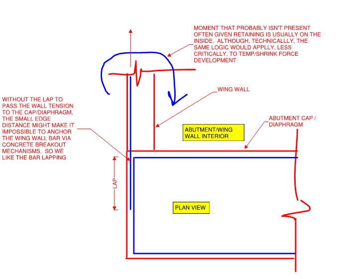
That would also explain a conundrum I've had with the details of our typical bridge abutments, and the reinforcing from the wingwalls into the abutment cap and diaphragm. The bars on the rear face of the wingwall and abutment are supposed to be lapped, but those in the front face of the wingwall that extend into the middle of the much thicker cap and end diaphragm, are only developed, since there's no reinforcing in the middle of the cap and diaphragm to lap them to. It's ok for the front face bars to be only developed because the concrete 'cover' is sufficiently thick in all directions that the bar is anchored. However, the bars in the rear face don't have enough concrete on the one side to absorb the tension force in the bar without failing and the bar breaking out, so they need to be lapped so that they transfer the force to other bar. I know it's a rudimentary example, but is it related to what you were explaining?
 
HR10 said:
Well KootK...I think what you're saying there makes sense.

Whaaaat?? Any chance you're single or, at the least, able to take a lover?

HR10 said:
...but what I hear you saying is that in order to be able to have the resistance of the full strength of the bar, it has to be able to transfer the force to the concrete (development) and the concrete has to be able absorb that force (anchorage) or transfer it to some other steel (lap)....Did I hit anywhere on the wall where the target is?

That was spot on.

HR10 said:
If we didn't have to worry about the second part, we wouldn't need to lap reinforcing - development of the bars would be sufficient.

Truly, I wish that I'd though to make that same argument myself in the course of prior campaigns. It's salient and difficult to refute.

HR10 said:
That would also explain a conundrum I've had with the details of our typical bridge abutments..

I'm afraid that I don't speak fluent Bridge. I'll give it my best shot though. And, if I've gotten it right, then I do believe that this is applicable to your conundrum.

c01_l6ycow.jpg


c02_m5adbt.jpg


HELP! I'd like your help with a thread that I was forced to move to the business issues section where it will surely be seen by next to nobody that matters to me:
 
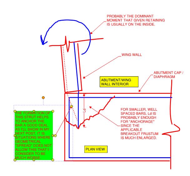
In my previous post, I highlighted some text in green because I wanted to refer back to it in this post. My strongly held belief is that:

1) the anchorage/development issue is much better when the distance between the flexural tension and compression is small relative to Ld. This would be the case for many things proportioned similarly to walls etc. This allows the tension bars to be effectively anchored back to the compression zone.

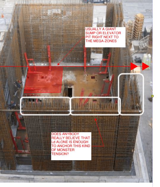
2) the anchorage/development issue is much, much worse when the distance between the flexural tension and compression is large relative to Ld. This would be the case with elements such as shear walls, as shown below. Here, the flexural compression zone stands no chance of being able to anchor the tension bars.

The shear wall example drives me nuts frankly. We expend gobs of computational energy sorting out performance based design, plastic hinges, etc for our sexy high-rises. All the while, my money says that half of these things aren't even stapled to their foundations properly. But Perfrom 3D says it passes so all must be right with the world.

And yeah, I get that the zone bars usually go to the bottom of the footings and that the footings are usually thicker than Ld. Still, though, given the consequences, I feel that the stakes are high enough for shear wall zone bars that their anchorage deserves some real attention. That, particularly given that it is rare for footings to be thick enough that the flexural compression zones can help anchor the flexural tension reinforcement.

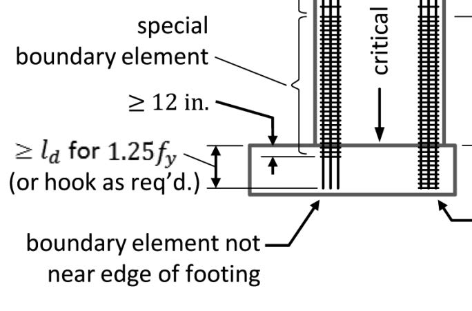
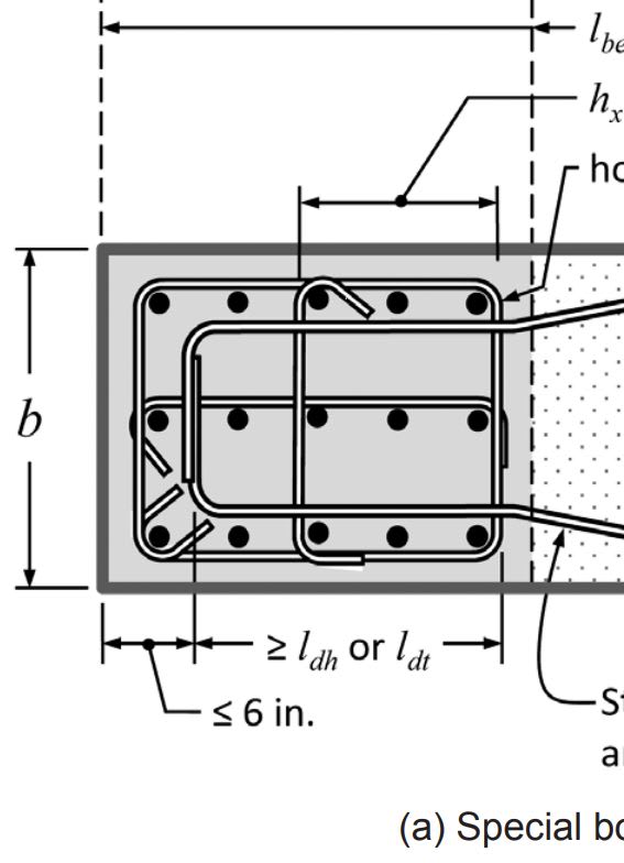
Check out the second sketch below from the NEHRP technical brief on concrete shear walls. Basically the best minds in the field telling designers to anchor their zones incorrectly. This is one of those areas where I feel that we need to acknowledge that the knowledge of practicing engineers is not just a subset of the knowledge of academics. Practitioner really do know some things that academics do not by virtue of our particular training and experience. And not just constructability / economic things.

c01_n1m27q.jpg

c02_h2w36s.jpg

c03_lnjfx7.jpg

c04_zfwhfw.jpg


HELP! I'd like your help with a thread that I was forced to move to the business issues section where it will surely be seen by next to nobody that matters to me:
 
Sorry KootK, I'm happily married (25 years this month, as it happens).

With regard to the bridge abutment, I'm afraid I didn't explain the configuration very well. I was referring to what we call an 'elephant ear' wingwall, where the walls extend parallel to and in line with the rear face of the abutment (perpendicular to the roadway for a bridge with no skew). The wingwall is 12" thick with the reinforcing in the rear face of the wingwall aligned with and lapped with the reinforcing in the rear face of the abutment. The reinforcing in the front face of the wingwall extends into the end of the abutment between the mats of reinforcing in the faces of the abutment, which is typically 2.5' thick.
 
HR10 said:
Sorry KootK, I'm happily married (25 years this month, as it happens).

Well congratulations! Happy after 25 yrs means that you've likely got yourself a true life partner. And that's a pretty big win.

HR10 said:
With regard to the bridge abutment, I'm afraid I didn't explain the configuration very well.

Got it.. elephant ears. It seems to me that my sketches above would still apply, however, just with the vertical wall element swung around to the sides of the cap/diaphragm. Agree?

HELP! I'd like your help with a thread that I was forced to move to the business issues section where it will surely be seen by next to nobody that matters to me:
 
The connection of the elephant ear wingwall is similar to the sketch, except there's no reinforcing in the end of the abutment, so no reinforcing crossing perpendicular to the developed bars through the concrete failure cone.
 
It probably would be a real problem, except that in-service there's generally very little soil in front of those wingwalls, so there's potential for only a small amount of tension in the front face bars.
 
At 2400 ft-k I think you have a basic overturning problem as well. Something like half the footing has lifted off the soil. Since it is rock, the stresses may be concentrated way out at the toe.

This messes with your shear distribution/resolution even more. It's not pulling anywhere near evenly and you don't have nice two-way punching shear. It's more one-way in the shape of an "L".

As an aside - when the footing thickness is less than the pier width, it doesn't look right. It doesn't look deep enough in the ground, either. Spidey sense is tingling.

 
Status
Not open for further replies.

Part and Inventory Search

Sponsor