Continue to Site

Eng-Tips is the largest engineering community on the Internet

Intelligent Work Forums for Engineering Professionals

  • Congratulations waross on being selected by the Eng-Tips community for having the most helpful posts in the forums last week. Way to Go!

Anchor Bolts In Bending Below Base Plate 3

Status
Not open for further replies.

dreber

Civil/Environmental
Feb 9, 2011
105
Hi folks, I couldn't find any guidance in the AISC 360, nor on my attempts at google searching, so I've invented a method and I thought I would run it by you folks for your input:

The Situation
I have a post welded to a base plate, the base plate is anchored to the concrete below via anchor bolts and leveling nuts. No non shrink grout here, just the anchor bolts to resist all forces.

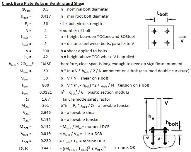
This is putting my anchor bolts into shear, bending, and tension, and I don't know of any specific provisions for checking the combination of stresses on anchor bolts. So, I just added up all of ASD level DCRs and summed them. Does this sound like an appropriate approach to you?
Capture_ok5het.jpg
 
Replies continue below

Recommended for you

Wouldn't you need to check the anchor bolts in compression from the moment couple as well?
 
My feeling is that it is probably quite conservative, usually any interaction would be the ratios squared (or to the power of some other factor) for LFRD for the shear and tension components.

For example in my regions code the tension and shear interaction is the sum of the square of the DCR's.

If you look at the interaction equations for member design it might give you some ideas to refine things further, a bolt could be considered as a solid circular section and normal member/sections checks undertaken (does it give a similar prediction of capacity). Alternatively working out the actual stress from first principles (i.e. von mises or similar failure criteria for direct and shear stresses) could be used.
 
Check out AISC Steel Design Guide 1. It can be found on google. Is there a reason you can't convert the moment to a force couple and just evaluate axial force and shear? The AISC design guide has a lot of good examples.
 
Section J3.7 (p. 16.1-109) of AISC 13th addresses combined bending and shear in bolts. That being said, combining the utilization ratios like you are doing (i.e. just adding them) is conservative. Adding the tension stresses with bending stresses is appropriate.


Tower Numerics has a really good Technical Manual for the design for monopole base plates. I found the following related to ungrouted base plated in there:
Bending Stresses In Bolts
Bolts in ungrouted base plates may be subjected to bending stresses when the clear distance below
the leveling nut is excessive. The TIA Standard has no requirement for this condition. However,
AASHTO requires bending to be considered whenever the clear distance is greater than one bolt
diameter. The ASCE Manual 72 recommends that bending be considered whenever the distance is
greater than two bolt diameters. The bolt is considered to be bent in reverse curvature. The bending
stress would then be
fb = (16*c*Fv)/(pi*db^3)
where c is the clear distance (see Fig. 3-4). When threads extend well into the clear space, the root
diameter of the threaded portion should be used for db.


This might be a little dated by now. But, it does demonstrate that there is literature out there. In particular, it would justify taking some of the conservatism off of your method and assuming double instead of single curvature. The double curvature assumption seems reasonable to me based on how restrained the bolts are top and bottom.
 
In the AASHTO sign spec., if the distance from the bottom of the leveling nut to the concrete is less than the bolt diameter, bending in the bolt can be ignored. For axial compression combined with shear, it's fa / 0.6 Fy + (fv / Fv)^2 < 1.0 and for axial tension it's fa / Ft + (fv / Fv)^2 < 1.0. ("^2" = squared).
 
Bobby46, I skimmed the table of contents for AISC Design Guide 1 and I think all of their examples assume a grouted base plate.

WARose, that's odd, AISC 360-10 (14th) seems to have omitted this method. I wonder why. Unfortunately, I don't have a copy of 13th. However, you are right about calculating the final DCR, so I will revise the method accordingly.

JoshPlum, thanks for the info! I don't have access to ASCE Manual 72, but I did find this PDF (linked next) which runs some sample calcs based on 72. I'll change my method to assume the bolt is in double curvature, which makes sense. However, this method seems to be using the nominal diameter as opposed to the root diameter? I'm sticking to checking my bending with root diam, which will be a touch more conservative. I'm also neglecting the fact that the nut will reduce the bolt's clear span, because what's a little steel among friends?

HotRod10, I don't have the sign spec, and without knowing what fa Fy, fv and Fv are I'm having a little trouble understanding. Is Fy = Fv? is fa a factored load?

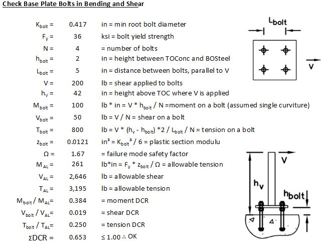
Anywhoo, here is my result. If I were really fancy, I would include some method to calc other bolt arrangements and/or use AISC 360-10 § H1 to account for super long spanned bolts, but this seems pretty good for this use case.

Capture_yrgdwl.jpg
 
"... without knowing what fa Fy, fv and Fv are I'm having a little trouble understanding. Is Fy = Fv? is fa a factored load?"

Sorry, I thought the nomenclature would be similar...Fy is the yield stress of the bolt, fv is the applied shear stress (factored in sign spec), and Fv is the shear stress capacity. (0.6 Fy if I'm remembering correctly, since I'm away from my desk at the moment). Anyway, I posted the equations just as an example of the way I've typically seen shear interaction with axial load calculated.

The equations actually include the (fb / Fb) term directly added, as with (fa / Fy), with only the (fv / Fv) squared. I didn't look at your numbers closely enough to notice the unsupported bolt length was more than the diameter.

 
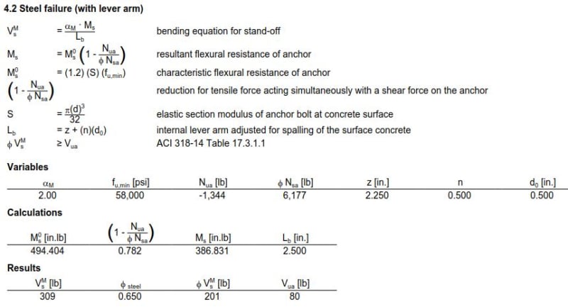
Hilti Profis has an option to check bolt bending when the baseplate has a standoff. They breakdown their methodology and equations in the Profis Design Manual. I haven't dug into it enough yet to know what they base their methodology on, but it's another resource you could look into and compare with your method.
 
Bolts in bearing-type connections subject to combined tension and shear are covered in Section J3.7 of AISC 360-10. The specification section number is unchanged from AISC 360-05. Strictly speaking, the provisions of Section J3.7 are intended for steel-to-steel connections but they are applicable to steel anchor rods.
 
ASCE Std 48 (replaced ASCE Manual 72) has provisions for this case with no grout. My ASCE 113 committee is tackling the topic. The first edition of 113 has equations for the anchor bolt stress but we are revising it for the 2nd edition. The big change is the length of the moment arm goes down into the concrete one bolt diameter. There is a European method that we looked at called ETAG that has equations. The concrete near the surface is not reinforced and cracks under the shear load and increases the moment arm.

A big topic of discussion in my ASCE 113 committee meetings is the exclusion of rod bending when the gap between the bottom of the base plate and the top of the concrete is less than 2 bolt diameters. In my 40 plus years in the T-Line industry, I have not heard of anchor bolt bending causing a pole failure but the younger committee members think bending should always be considered. Technically, it should be considered from a mechanics standpoint, but practically, the old timers say you can neglect the bending because we have not seen a problem. Now, as soon as I say that, there will probably be 100's of replies saying "I saw it happen". :)

_____________________________________
I have been called "A storehouse of worthless information" many times.
 
HotRod10, thanks for the clarification.

bones206, now you've got me all curfuddled. I just ran this case in HILTI (with LRFD laods as opposed to the ASD loads in my example above) and this is the section on steel stresses due to bending in the bolts. Did they get this method from ASCE 48? Full Calculation

Capture_b5xawq.jpg


Hokie93, thanks for the clarification, but I still don't know how I would apply this to a calculation including the moment on the anchor bolt.

transmissiontowers, Thanks for the info and the leads on additional resources. If we neglect the reduction in clear span caused by nut below the plate, do you think we can neglect the addition of clear span caused by concrete crushing?

Alternatively, we could develop a spreadsheet that would consider the actual shear forces and the actual concrete strength, to estimate the amount of concrete that was crushed. In this way, we could do our best to calculate exactly the clear span of the bolt, and then include the moment on the bolt, because it seems to be the more accurate way to go. The lack of failures over the last 40 years are likely due to safety factors, overstrength in materials, and conservative engineers. Would it not be appropriate to analyze the bolt as accurately as possible, and then go back and reduce some of the overly conservative approaches that are used in the development of loads and safety factors?
 
I think in most pole type or transmission type situations, the shear is usually not that large in proportion to the moment so I can understand why it has not been an issue. Additionally, if the base plate is grouted, then the bending will cause friction which will tend to resist the shear. If you are dealing with a column that is part of a braced frame, then I can see it being a bigger problem.
 
I believe Hilti Profis is using the ETAG method that transmissiontowers mentioned. See pages 197-215 of the Profis Design Guide: Link

 
dreber: Can you upload this without using google drive?

Thanks, Dik
 

XR250, for grouted applications, I tend to worry less. In the ungrouted application of 1/2"Φ bolts below a simple guardrail, with a 2" ungrouted space, the moment DCR is commensurate with the tension DCR, and it seemed worth bringing to the attention of you fine folks.

bones206, It makes sense that HILTI would use the ETAG method.

dik, I have changed the file permissions to allow anyone to access the file. That should fix ya.
 
In my T-Line and Substation industry, we got away from grout under the base plate and let the hollow columns "breathe" and let the water out. I'm sure it is fine in an industrial frame with a roof and not much chance of water infiltration. We have had several cases of columns filled with water over 5' high which rusted the hollow column from the inside out in an outdoor substation because the grouted base plate kept the water trapped inside. I have also seen non-hollow column-type members rust the anchor bolts in the grout. We use base shoes on large towers with L8x8x1 legs welded to a thick plate on anchor bolts with leveling nuts with grout (these are to make the elevations equal across the tower). The water infiltrated under the plate thru the annular gap between the bolts and the 4 bolt holes in the plate. The wet condition rusted the bolt under the bottom nut which we found when we tried to replace the cracked grout. The grout was dry packed from the edges of the 18" square plate and there was space to collect water and rust the bolt. Sorry for the unrelated info on grout, but I guess I just felt like sharing. :)

So anyway, the bending in the bolts under a thick plate is always theoretically there and I don't have a technical leg to stand on to say we neglect it when the gap is small but it has worked for many years and is indeed acceptable in the ASCE 48 Standard. With the coming publication of my ASCE MOP 113 not allowing the practice, ASCE 48 may remove it in future revisions. In our industry and my part of Texas, we design for a hurricane wind that may give an event that loads up the structure to maximum once every 50 years (or 100 or 300), so we may have gotten lucky. You are correct for tall T-Line poles, the shear is relatively low compared to the base moment, but we also have bus support columns that are 20 feet tall on 4 bolts, so we run the gamut.

If you consider the gap between the bottom of the leveling nut and top of concrete is one bolt diameter (when ASCE 48 says you can neglect bending), we assumed the bending was more of a shear load because the moment arm is so short and equal to the diameter. When you allow the bolt moment arm to go down 1 diameter into the concrete like the ETAG method does, it probably should be considered (according to the majority of my committee).

If you are a professor at a University and teach steel design and have unlimited time to consider the minutia of stress in round bending members (including threads) with short moment arms and have the resources to mesh up a base plate and all the anchor bolts (with threads) and leveling nuts into a mesh of concrete that can crack and give up support for the round bending member, then you can spend 6 months analyzing one base plate connection.

In the practical world, we take the loads on the connection and come up with a few equations that cover the worst case and pick out a 2.25" diameter anchor bolt (we now have to call them rods) and hope the construction workers install the base plate with a gap that is smaller than the one we designed it for.

In order to neglect the bottom nut, you have to assume that the base plate is rigid enough and clamped tight enough by the top nut so the bolt forms an "S" shape like a fixed-fixed simple beam with an inflection point from the bottom of the nut to 1 diameter into the concrete. With this reduced moment arm, you can run through an interaction equation that considers the shear, axial, and moments in the anchor rods and pick out a rod diameter (assuming again that they are all equally loaded) If you are going to all the effort to make assumptions about concrete crushing (testing has shown that it does exist), then I think the shear at the bottom of the bottom nut is appropriate.

I believe the original ETAG method considers the shear to act at the center of the top base plate and consider the anchor rod as a simple cantilever from there to 1 bolt diameter into the concrete. My committee considered this to be too conservative and we are adopting the clamped base plate model I described above.

Our committee goal is to give some interaction equations that are easy to put in a spreadsheet or Mathcad app (or if you are ancient like me, into a Fortran program) so you can go about the process of designing safe connections to concrete foundations without spending 6 months on each column connection.

Sorry for the long post, but I don't get an eMail when someone responds to a topic even though I have the Notify Me box checked, and I just came here to look to see if someone responded.


_____________________________________
I have been called "A storehouse of worthless information" many times.
 
I looked in my spam folder in my Gmail and found the notices that someone replied to my post in there, so Maybe I will start responding sooner.

_____________________________________
I have been called "A storehouse of worthless information" many times.
 
You could just go to the original ETAG analysis and use their methods - which were researched and approved in Europe. You can also use Hilti's program or Simpson's program. Before those methods came along, I developed some sort of analysis where I never let the concrete crush and did use a triangular passive type pressure diagram to determine the center of force and come up with a lever arm. I didn't like to accept the clamping arrangement as I didn't have any control over the field installation. Most likely the bolts may be "overdesigned" by others, but if there was ever an "event" and an investigation, then I had a rational approach. I have always been leery of the "we've always done it this way" approach. I don't believe the ASCE 113 anchor bolt committee were able to document where the clearance minimum originally came from. I have never liked to rely on grout and always stayed away from it structurally. When I did communication poles, there was always a detail of sort for a water drain. Poles do sweat and can be a corrosion problem unless they are galvanized. This is a problem in really big poles - say in the four hundred foot range.
If we're talking about stress reversal due to say, a seismic event, I've always been concerned about progressive crushing of concrete and possibly lengthening of the moment arm.
Sorry to mix poles with structures. Depending upon the type of structure being anchored, one should be cognizant of thermal movement of some structures' base plates. Thermal movement crushing damage is usually hidden.
 
Status
Not open for further replies.

Part and Inventory Search

Sponsor