Eng-Tips is the largest engineering community on the Internet

Intelligent Work Forums for Engineering Professionals

  • Congratulations waross on being selected by the Eng-Tips community for having the most helpful posts in the forums last week. Way to Go!

Anchor points in piping 5

Status
Not open for further replies.

sider

Mechanical
Nov 26, 2021
43
GB
Hi all,

could use some advice on anchor point topic.

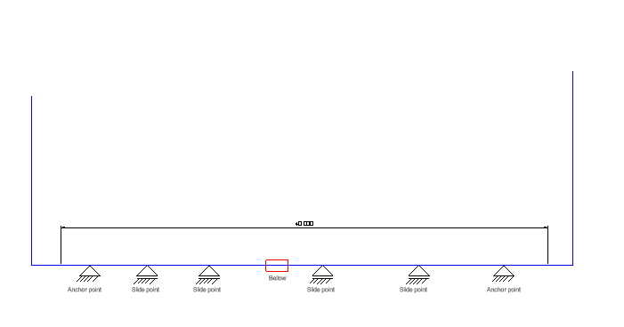
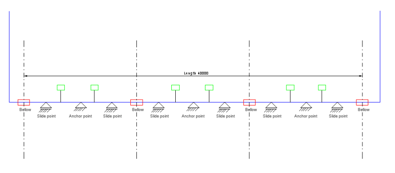
From my understanding, when an expansion joint is installed in the piping system, it must be located between 2 anchor points ( we are talking about a straight line of CHW piping, 40 m long, the difference between installation and working temp around 25°C ).

Based on conditions in piping, both working and during testing, the calculation gives me that for DN150 there has to be an anchor point with 26000 N (testing done on 10 bar). I am going through different manufacturers of anchor points, however, just couldn't find any anchor point to take upon such load. What kind of anchoring do you usually use in such cases?

BR
 
Replies continue below

Recommended for you

Your post is confusing. Expansion joints are used in piping systems to absorb thermal expansion or terminal movement where the use of expansion loops is undesirable or impractical.

Can the piping be designed so that no expansion joint is necessary?
 
A diagram or sketch would help.

"expansion joint"?? Do you mean a bellows?

As soon as you anchor something then you have a reaction force when the temperature changes. can't you let the ends move a few mm?

Where is 26000N coming from?


Remember - More details = better answers
Also: If you get a response it's polite to respond to it.
 
Anchor_point_sketch_ovth2b.png


Yes, the expansion joint/bellow is used for that purpose, and it can not be avoided.

Regarding the anchor point, yes, I am aware that there is a reaction force during temperature change, however, there is also a reaction force during pressurization of bellow, which was calculated by multiplying "internal pressure" x "bellow effective area".

Also, not visible on the sketch, there are connections to cooling units, and I am not sure is it wise to let the CHW piping move "few mm" since that could affect those connections and possibly put a strain on them.
 
You are correct. An anchor is needed on each end of the joint.

If the diagram is correct, I question the need for the joint.
Why do you think a joint is needed? Stress on the chillers?

I cannot make out the length dimension. Looks like 0, but the dwg indicates that it could be kind of long. As such, it appears that you can add all the loops needed to have adequate flexibility without using an expansion fitting.

Where is the overstress occurring, if you do not use the expansion fitting?
Something is telling me you did not do any analysis yet and have just put in a joint because you THINK it is needed.

It would be nice to see a diagram going all the way to the chillers, with real dimensions.

A black swan to a turkey is a white swan to the butcher ... and to Boeing.
 
I would recommend a expansion 'loop' versus the bellows. If it has to be a bellows, don't skimp and make sure it is robust and can take the pressures it could see under adverse conditions (especially where a PD pump can be reversed).
 
Due to the allowable space, it is not possible to make an expansion loop, and therefore, bellows must be used. On each end of the CHW piping will be a riser going to the roof. Also, not shown on the sketch, on both ends before risers there are additional bellows(modular construction)

Taking into account risers, which will have pipe clamps symmetrical to the axis of CHW piping shown on the sketch, they will take up the force exerted by pressure and thermal expansion.

The guides on the long piping run will ensure that there is no buckling and that piping can move along, however, I would also like to include anchor points between the individual bellows to ensure fragmentization of piping, so every individual section works for itself.

If somebody can give a few thoughts about this idea? Also, my questions on 1st post still stand. How do you ensure clamping of such force in anchor, in this case, 26 000 N?

Thanks for the answers so far
 
The anchors should be as far apart as possible to capture maximum expansion, but not so much as to exceed bellows movement allowance.

You may have to construct your own anchors to resist the large forces. I use a thick concrete wall, similar to a retaining wall, but thicker for punching shear, in which an anchor flange is embedded. The pipe is welded to each end of the flange.
628_507153_anchor%20flange5.jpg


Don't spare the rebar around the flange.

Use guides rather than anchors in other locations.

A black swan to a turkey is a white swan to the butcher ... and to Boeing.
 
Anchors on piping need something welded to the pipe and then bolted or fixed into something solid.

We can't see what you can see so don't know what your anchors or supports are sitting on?

Also your bellows can be restrained to not exceed certain expansion or contraction limits so that you don't get the end cap force if this is the force you've calculated?

Remember - More details = better answers
Also: If you get a response it's polite to respond to it.
 
Ahhhh ...

"Due to the allowable space, it is not possible to make an expansion loop, and therefore, bellows must be used."

We have found the problem and it is the same problem we have found so many times before !!! ..

Incompetent piping design ...

Competent industrial piping designers understand thermal expansion and route piping accordingly

When asked to route piping systems, architectural designers move bushes and trees around in the plan drawing and, of course, will stare at you with their mouths open...

MJCronin
Sr. Process Engineer
 
That doesn't really seem to be a fair assessment at all MJCronin.

Sometimes there is literally no space for an expansion loop, due to steel conflicts, other piping/utilities in the way, etc. Sometimes you have to thread that needle and suck it up and deal with an expansion joint.
 
First, I never said that I was fair ... I only want to present and alternate opinion. ... Over and over, I am stressing an opinion !!!

Reasonable and bright engineers can certainly agree or disagree with me based on thier knowledge and experience.

I learn things when people disagree with me and clearly express their reasons for doing so ...

Second, I have been an engineer for over fourty years and reviewed and routed thousands of piping systems ...

When you state that there is "Sometimes there is literally no space for an expansion loop," you are talking about the one case in a thousand ... IMHO

This does not happen with every other piping layout !!!! .... I still strongly sense incompetent piping designers

I can only recall two or three times have I ever seen a mid-piping system expansion joint used

Again, .... This is my opinion

MJCronin
Sr. Process Engineer
 
You are not alone.

I can't even see any equipment on the sketch. What's to protect? The Pipe?

The length doesn't matter to stress, which is the same for any length.
10bars (150 psi) is the lowest steel pipe pressure class.
Diameter is 150mm (6 Inch), not huge by anyone's standards.
ΔT a whopping 50C° (122F°), not that much really.
Thermal expansion 1.25 INCHES (31mm)
PxA = appx 4600 POUNDS (20,500 N), OK say 26kN, basically nothing as far as pipe loads go.
A full thermal restraint is probably 100,000 Lbs (445,000 N)

Let the pipe grow thermally (no expansion bellow) and thermal axial stress is 0.
Height to the roof might be enough flexibility right there. It's one big expansion loop.


A black swan to a turkey is a white swan to the butcher ... and to Boeing.
 
Agree very much with 1503-44 ...

This is not the gawddamn Main Steam system in a Combined Cycle plant ... This is not an alloy steel system operating at 2000+ psig and 1150F !!

This is a small-bore plain vanilla piping system ....

..... and, I am guessing here, the first piping system that the OP has evaluated for thermal expansion

No ???

MJCronin
Sr. Process Engineer
 
I think not evaluated yet (other than by us).


A black swan to a turkey is a white swan to the butcher ... and to Boeing.
 
Hi all,

thanks for the info so far.

I see there are some open questions so I attach a more detailed sketch now. I am aware that as MJCronin mentioned this is probably a "plain vanilla" system for piping engineers such as you, however best practices advice would be much appreciated.

Sketch_t8uztj.png


So, the situation is: 40 m piping, small temperature difference (25 °C thermal difference), bellows on locations illustrated on the sketch (used because the piping must be disassembled and assembled later on because of modular construction), and green squares are connections to equipment. As mentioned before, the bellows cannot be avoided. I have put an anchor point between those bellows and my question is:

1. Are those anchor points necessary? If we put all slide guides is it just fine to achieve the reaction force of risers fixing points?
2. If we use sliding guides instead of those anchor points, is there a possibility of stress on equipment connection points since they are fixed, and the piping is moving in an axial direction because of thermal expansion)
3. Will calculation of reaction force consists of 2 cases: 1st when there is testing pressure and 2nd when there is working pressure+thermal expansion+friction force from sliding guides?
4. Is there something I am not accounting for?
 
The details of how and what you are connecting and the dimensions are important. How far away from the DN150 and connecting pipe diameters and wall thicknesses of all.

What operating temperature and pressure?

Test pressure is done cold. No thermal stress.

You do not know if bellows are required. Why do you insist on having bellows? That should be your last option. Why not bolted flanges?

Everything you add an anchor, you increase pipe axial stresses. Each pipe will have the same 445 N axial compressive load stress, except for the pipes and anchors at the ends. Each interior anchor will have approximately balanced loads from the pipe to the left and to the right.

Only the end anchors will transmit the 445N loads through the anchor to the ground.


A black swan to a turkey is a white swan to the butcher ... and to Boeing.
 
The straight line is DN150(wall thickness 4,5 mm) and connections are DN50 (wall thickness DN3,65 mm). Unfortunately, right now there is no more detailed design, however the connection will be on top of the DN150 pipe and going to equipment which is 4 m away, so some bend will be included in the design.

The operating temperature is 12 °C, pressure is 6 bar. Bellows are used to connect different piping modules if there is a slight coplanar difference between modules installation on site.

Can I ask why you strongly advise against bellows? Are there particular issues when such is used in the piping?

Also, how did you get to 445 000 N you mentioned in the previous post?
 
Maintenance headaches. Always leaking.

A decrease in temperature is a stress reversal from temperature increase. Instead of compressive load, it becomes a thermal tension load, as the pipe contracts. If unrestrained, your 6" pipe will decrease in length by 30mm.

445kN was my estimated thermal load.
ΔL = 9/5 x 0.0000065 x pipe length mm x ΔT C°
ξ = ΔL/L x E = 1.25in/(40m x 3.2808 ft/m x 12 in/ft) = 1.25 in
Stress = 1.25 in/ 1575in * 30E6 psi = 23,812 psi

I estimated pipe steel area as 5 in2 from a 1/2" thick wall.
Load = stress x area
23,812 x 5 = 119,000 lbs x 4.45N/lb = today 530 kN
Use the area for your 4.5mm wall thickness. It will be smaller load.
That tension load will be in the pipe between every anchor. It will be trying to pull your bellows apart, which is why you need anchors.

If you didn't have bellows, you probably wouldn't need anchors, but since you do, you do.
If you didn't have anchors, the pipe would only contract 30mm/2 =15 mm from each end of the DN150 towards the center.

The equipment in the center would see almost no movement at the DN150. the two farther away would only see about 1/2 of the 15mm movement along that 20m making it a 7.5mm movement there.

7.5mm movement of the connection isn't all that much, but it will add some bending in the 4m pipe. What's the fixed end moment of a rigid ends beam 4m long where ends have a 7.5mm relative end movement? Maybe not all that much.


A black swan to a turkey is a white swan to the butcher ... and to Boeing.
 
"Can I ask why you strongly advise against bellows? Are there particular issues when such is used in the piping?"

Why ?...Because it is poor piping practice AND expensive .. Most EJs are placed at the termination of the system ...

We are not against the use of bellows, per se .... But we are not against the delivery of daily newspapers by a bulldozer either

EJs are commonly placed where a piece of equipment cannot take piping reaction loads from typically "hot" piping ....

You do not have hot piping, Najeeb ... You do not even have an extreme system .... You also refuse perform a detailed piping stress analysis using an acknowledged piping analysis program such as CAESAR II

Read up a little here and ask better questions ...


Also, since this is your first piping system design, you should figure out how to draw piping isometrics for later analysis


MJCronin
Sr. Process Engineer
 
Status
Not open for further replies.

Part and Inventory Search

Sponsor

Back
Top