Continue to Site

Eng-Tips is the largest engineering community on the Internet

Intelligent Work Forums for Engineering Professionals

  • Congratulations cowski on being selected by the Eng-Tips community for having the most helpful posts in the forums last week. Way to Go!

Anchor reinforcement for a stem wall 1

Status
Not open for further replies.

RabitPete

Structural
Nov 24, 2020
109
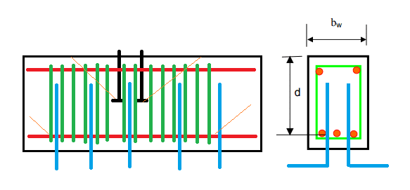
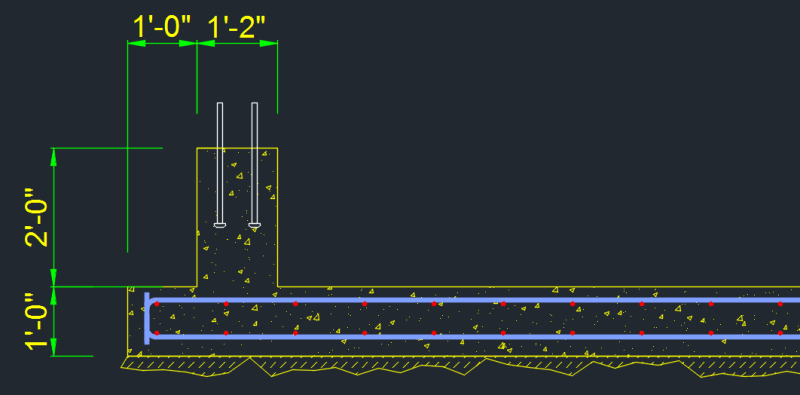
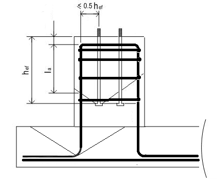
I need to design a reinforcement to resist moment loads from the column on top of a stem wall. There is a lot of information out there on anchoring to pedestals, but not so much when it comes to rectangular footings. Concrete breakout is a controlling factor, so I am adding vertical reinforcement with loops encircling entire width of the wall on top and standard hooks at the bottom. My issue is that bottom footing is not deep enough to resist the breakout either.

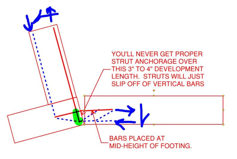
What would be an effect of adding longitudinal reinforcement to the stem wall, may be make a section of it into a beam? Would it help to distribute the load from the anchors over a longer footing area, so steel which is farther away than 1/2Hef from the anchors would also contribute?

anchor_kazjh6.png
 
Replies continue below

Recommended for you

WARose said:
I've generally observed the 3 bar diameter spacing in the code for hooks (without using the allowed reduction). I don't know if that meets Kootk's "Generously spaced" criteria.....but usually problems show up elsewhere before that becomes one.

Nope. Obviously, the problem isn't going to show up if you're not checking for it.
 
So what is the Kootk recommended spacing? (Before problems show up from development alone.)
 
WARose said:
how does the wall footing handle this much shear? Say you've got 4 #5's closely spaced.....that sends nearly 75 kips of force into the wall footing
Yeah, its going to be a problem if it sends it over 8"x 8" area. That's why the first question is how the load is distributed along the wall, as 75 kips along 10ft is only 7.5 kips/ft. I am having a hard time imagining that only area directly under the anchors will see the load. What do you guys think? Or any tricks to make sure stem wall distributes point load over the entire length of the footing?
 
I am having a hard time imagining that only area directly under the anchors will see the load. What do you guys think? Or any tricks to make sure stem wall distributes point load over the entire length of the footing?

I'm not sure what your stem wall height is (or it's width) but eyeballing the pic....with such a short height (relative to the 20' length) combined with such a thin footing....I think the odds of the shear & moment equally distributing (in magnitude) over the full length are pretty low.
 
Would something like this work? Anchors extend to the middle of the stem wall, stirrups are fully developed both above and below anchor heads, so they pickup full load and transfer it to the stem wall which is now designed as a beam, and then several fully developed 90 degree hooks transfer the load down to the footing. So the original breakout cone is not only extended, but its reinforced by 5 well spaced fully developed hooks. Any flaw in my load path?
beam1_mhdv5l.png

P.S. The stem wall is 24" tall and 14" wide. Illustrations are not to scale.
 
Not a bad idea....the distribution would still be a question (i.e. how much shear winds up in elements attached; FEA could resolve).

You could always use shear reinforcing in the footing.
 
WARose said:
So what is the Kootk recommended spacing? (Before problems show up from development alone.)

I don't have one I'm afraid. For me, it's more about trying to distinguish between situations that are characteristic of anchorage versus those that are characteristic of reinforced concrete design. The reinforced concrete stuff basically means anchorage being provided by a compression strut coming into the development region at a reasonably shallow angle, consistent with how the development length testing is carried out.
 
RabitPete said:
However what we are not considering is a compression force from the moment arm

There are anchorage design provisions that give account to that benefit. If you want to explore that and have trouble finding the provisions, let me know. Basically, it turns the governing mode from tension breakout to something more like pryout, as you'd expect.

RabitPete said:
I am even more concerned with load distribution and soil bearing. While overall moment per ft of length is relatively low, I got a single concentrated moment applied in a middle.

That doesn't bother me at all. Your latest sketch is basically what I was getting at when I made the statement below. And, with a defined reinforcing path, I'd be perfectly happy to open that up to 2:1 or more. Beyond the anchorage, I see this is a plastic system capable of considerable redistribution.

KootK said:
1) I feel that your logic is sound with that and that it could be made to work with the right attention to detail. Even without the beam detailing, it's pretty common to assume a 1:1 load spread from your base plate down to the footing for bending.
 
This is for the design of stem wall reinforcement to resist the applied loads. Not for the anchorage.

1) Assume the concentrate load is longitudinally spread over an effective length, which is a 45° spread on each side of the load.
2) Get soil pressure under the assumed strip.
3) Turn the stem wall up-side-down, now you have a loaded T-beam to design for.
 
KootK said:
There are anchorage design provisions that give account to that benefit. If you want to explore that and have trouble finding the provisions, let me know. Basically, it turns the governing mode from tension breakout to something more like pryout, as you'd expect.
Please share, I know I have read that their is current research being done on this that the ACI plans to incorporate in future revisions, but I hadn't seen anything that is available now.
 
Sure, it comes from this document which, as I understand it, is kind of the source document for AppD: Link

In summary:

1) Work done by Zhao in 1993. I couldn't get my hands on the original stuff.
2) As expected, for the right combinations of lever arm versus embedment depth, there are marked improvements.
3) There's a proposed evaluation method but it requires determining a parameter (z) based on an elastic analysis. Not sure what to do with that in practice.

C01_l2ah0r.jpg


c02_pi64v4.jpg


C03_waxsve.jpg
 
Thanks for sharing - more reading material for me to get through. Maybe I'd have more time for this sort of thing if I could only stop myself doing things like redrawing lines through bricks.
 
Sure, it comes from this document which, as I understand it, is kind of the source document for AppD...

Not to nitpick but I think Appendix D evolved out of ACI 349 (Appendix B) first (before Eligehausen's book came out).

I have that reference....excellent source.
 
For a shallow footing 12" or so deep, do you guys see any issues with detailing a single layer of reinforcement in a middle (assuming moment capacity checks out)?
 
rabitpete said:
For a shallow footing 12" or so deep, do you guys see any issues with detailing a single layer of reinforcement in a middle (assuming moment capacity checks out)?

I think that it can be done but there are challenges to be addressed:

1) Your one way and two way footing shear capacities will be halved.

2) Within the joint, you've compressed the geometry substantially which will amplify the shears there.

3) You'll be inviting a lot of top side footing flexural cracks right where you'll have your mission critical tension breakout frustum.

4) The side of the footing that would be resisting uplift will have a very challenged shear joint where it ties into the vertical tension bars which will be, effectively, hanger bars at that location.

For these reason, I'd much prefer two layers of rebar myself.

 
Makes sense, just trying to find the most cost effective solution. Typically, upsizing rebar or decreasing spacing on a single layer is a lot cheaper than additional labor of putting 2nd layer. And it is not just a stand alone footing, it extends further and becomes a floor slab, kind of a flexible mat foundation, so the area is somewhat large. I was also thinking of adding a 2nd layer just under the column, a strip about 4 ft wide (assuming a conservative 1:1 distribution from 24" stem wall) and all the way across. Red rebar on the plan is a top layer, the remaining area has bottom steel only. Something does not feel right about it making me think it might crack near transitions between dual and single layers

rebr_cs2v5o.png
 
1) It would be a great help if you could post a section through this drawn to scale.

2) Based on your last sketch, it seems as though the portion of the footing to the left of the column would be of little relevance other than to help with development and anchorage of the bars on the right.

3) I'm sure that regions where the reinforcement scheme changes are slightly more prone to cracking but this is something that is done all the time without incident so I'd not worry about it.

4) I understand the economic advantage of a single layer of reinforcing. That said, it only works if it works.
 
Here you go (minus anchor reinforcement). Yes, 12" portion of the footing to the left of the stem wall is for anchorage and development.
rebr1_ivm2ne.png
:
 
Thanks. In my mind, this arrangement means that:

1) You will be counting on the opening behavior of the joint to resist the overturning associated with outward shear.

2) Centrally placed reinforcing isn't likely to pan out for the opening moment as shown below.

c02_yl7awb.jpg
 
How about turning the L other way around like you suggested in earlier post? Would not we also need to worry about development length in compression for the vertical bar on the compression side? That alone would dictate a deeper footing or may be a 2" thicker section under the wall only
 
Status
Not open for further replies.

Part and Inventory Search

Sponsor