Continue to Site

Eng-Tips is the largest engineering community on the Internet

Intelligent Work Forums for Engineering Professionals

  • Congratulations SSS148 on being selected by the Eng-Tips community for having the most helpful posts in the forums last week. Way to Go!

Anchor reinforcement for a stem wall 1

Status
Not open for further replies.

RabitPete

Structural
Nov 24, 2020
109
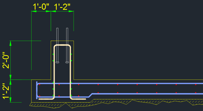
I need to design a reinforcement to resist moment loads from the column on top of a stem wall. There is a lot of information out there on anchoring to pedestals, but not so much when it comes to rectangular footings. Concrete breakout is a controlling factor, so I am adding vertical reinforcement with loops encircling entire width of the wall on top and standard hooks at the bottom. My issue is that bottom footing is not deep enough to resist the breakout either.

What would be an effect of adding longitudinal reinforcement to the stem wall, may be make a section of it into a beam? Would it help to distribute the load from the anchors over a longer footing area, so steel which is farther away than 1/2Hef from the anchors would also contribute?
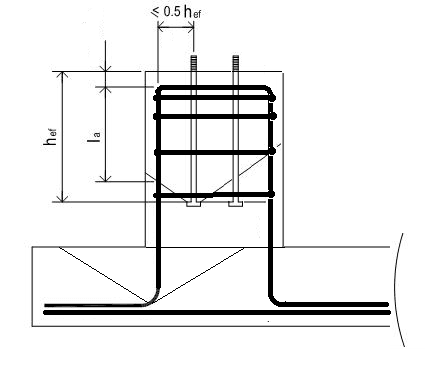
anchor_kazjh6.png
 
Replies continue below

Recommended for you

RabitPete said:
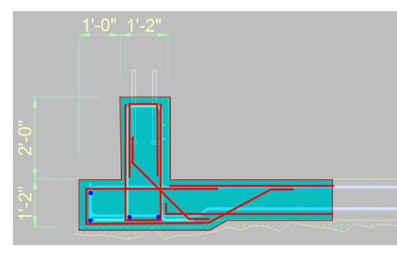
How about turning the L other way around like you suggested in earlier post?

I don't see it:

1) While there is a preferred hook direction from a mechanics perspective, the strut and tie model is agnostic to hook directions. It's just part and parcel of generic hook development.

2) As you can see, there's a strut coming in from both directions requiring restraint. A single hook wouldn't be able to restrain both struts unless you're alternating hooks etc.

3) My earlier proposal wasn't a hook but, rather, a lapped rebar bend around a corner. You could do that here but that would require moving the hook legs up to the level of the centrally placed rebar. And that would obviously weaken the tension anchorage.
 
RabitPete said:
Would not we also need to worry about development length in compression for the vertical bar on the compression side?

Only if you actually need to utilize the bars in compression. I very much doubt that's the case.
 
You're only doing this at a local area so maybe just go with the Cadillac and be done with it. Potential detailing problems with yours:

1) Hooks facing the wrong way.

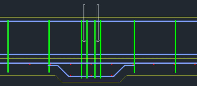
2) Unrestrained tension kinks in your footing bottom bars.

For less critical applications, one can certainly back away from my detail towards yours. That's a matter of judgment though: yours.

C01_xyh1ej.jpg
 
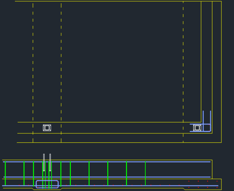
Yeah, I did not like the offset bend in the bottom bar either, smelled like trouble. Actually it is not just one localized area, there are 12 of those along the wall, and then there is also a corner. I only showed 1 middle column. I like the idea of U shaped reinforcement to make the hooks face inwards without having separate bars all next to each other.

Another option might be to extend a thickened 14" section all the way to the right. I have to do some math, but with 14" thickness and 2 layers, it might only need to be 36 or even 24" wide, the idea is to get it long and wide enough to keep soil bearing pressures under control. I have not even accounted for the rest of the slab which will surely share some of that load too.
 
Here is what I meant, may be make a 3ft wide x 14" deep grade beam centered under each column to help with distributing moment over a larger area of the slab? 2 U-shaped ties on each side of each anchor (as per KootK details), standard L hooks 12/24"OC along the remaining section of a stem wall. Something about that rebar piercing the grade beam feels neither right no elegant. Every time I think the good solution is here, it seems to be slipping away...
view1_qmie1q.png
 
Could someone please explain a little or point to a good source of information on the compression strut-tie system. What shear forces do we need to deal with? Would not I have to add shear reinforcement between compression/tension sides and the same thing in the other direction, so moment in both directions transfers from anchors to the beam?
 
I am still struggling to come up with a good and simple solution. As the moment can be reversed and also applied in the orthogonal direction, I always end up with some hooks pointing not in the optimal direction.
And as far as U hooks go, should not the U be at least as wide as 2x standard hook lengths for it to be fully developed in tension on both sides?
 
Sorry, we dropped the ball on this one. If you haven't yet resolved this, report back and we'll try to get it sorted over the next few days. Fundamentally, I feel that your long, thin strip foundation proposal is a little weird and perhaps ill advised. That said, maybe I don't fully understand your intent with that.
 
This is more of a thin mat foundation, not just a strip under the wall. So the idea was to utilize that entire slab to keep it from overturning or exceeding soil bearing capacity. I posted some of the 3D details in another thread, but cant say I am happy with those. What I have so far is a T-shaped thickened section (14" deep, 36" wide) under each column. I would rather see that moment fully transferred into the stem wall and then distributed over a larger area of the slab, instead of taking it straight down into the slab and relying on a small core.
 
KootK:
Your prolific posting has been great gain to many, including myself - particularly for reinforced concrete and challenging anchorage problems.
Thank you and keep it up.
My one complaint: your posted sketches look like you're blindfolded, writing upside-down, using a turd stick. We can take a collection here on eng-tips and get you a better drawing program.
 
ATSE said:
My one complaint: your posted sketches look like you're blindfolded, writing upside-down, using a turd stick. We can take a collection here on eng-tips and get you a better drawing program.

1) Duly noted.

2) With regard to a drawing program, what would you recommend? I use Bluebeam for this stuff currently. I also have AutoCAD and Revit but don't find either of those option to be speedy enough. Like most, I'm threading this pro-bono stuff in amongst the assignments that pay the bills.

3) I've been operating under the assumption that the main thing about forums sketches is that they be made to exist in the first place, regardless of their quality. So, as long as I'm able to get my point across, my second prerogative is expediency. There was a time where I was known for the quality of my hand sketches here on Eng-Tips. Some miss that and I miss it too. For speed though, Bluebeam really speeds things up for me which allows me to do more at a lower cost. Being able to take OP sketches, screen them down, draw over them, and upload them here in a minute or two is a game changer for me.

4) If you'd kindly start that collection, I'd be totally game for a Tekla license.
 
Status
Not open for further replies.

Part and Inventory Search

Sponsor