Eng-Tips is the largest engineering community on the Internet

Intelligent Work Forums for Engineering Professionals

Anchorage Connection Between Sill & Block Wall 5

Status
Not open for further replies.

zero1238

Structural
Oct 6, 2017
68
0
0
US
This is a unique one...

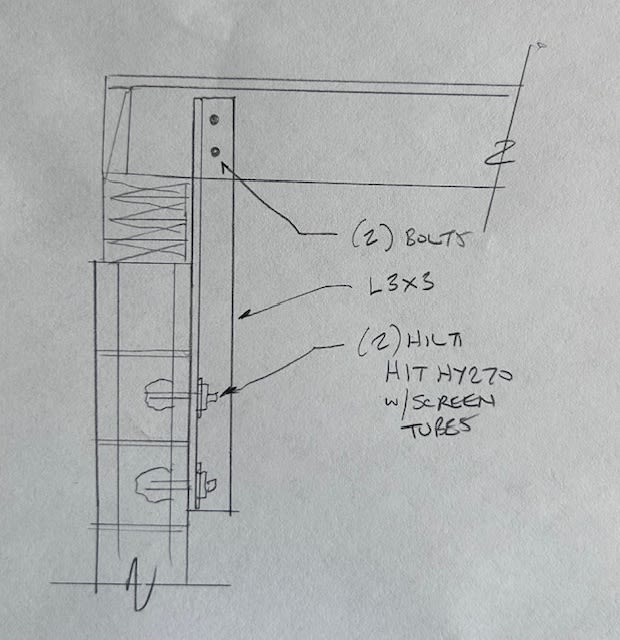
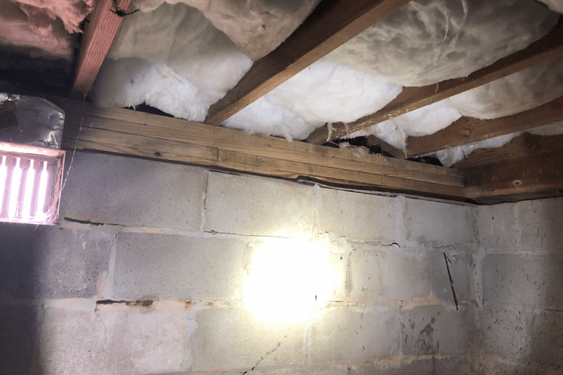
Looked at a house in a flood zone that was built upon a crawlspace with an ungrouted masonry block wall and four (4) 2"x6" sill plates between the 8"x16" block foundation and 2"x8" floor joists. I also found out that there is no anchor bolts at all so I am trying to specify a connection between the block and the sill but I am coming up empty. I've tried the Simpson FRFP, URFP, and FJA and can't seem to get them to work for this application. I even called Simpson Strong Tie and they said they didn't know of something they could specify. Has anyone ever run into a scenario like this and if so, what did you end up using to fasten everything together???

Sill_Plate_Picture_axoems.png
 
Replies continue below

Recommended for you

I would consider vertical and diagonal angles with post installed anchors into the CMU and lag screws into the sill. It looks like you will need to pack out the sill to be flush with the inside face of the CMU.
 
@JAE I feel like these Hiltis would have pretty low capacity, but I don't have a better solution. I guess I just wanted to say this in case OP was looking for a high load-bearing solution.
 
Why not use the simpson plates into the first ply and then drive screws through all plies to tie them together? Access will be tight, but there are tools to do that job pretty easily.
 
Masonry walls can be real fun to try to engineer. Are you designing for uplift or transverse loading?

If uplift, something like the sketch above would work. However, you will likely need to assume that the cores are not grouted and there is no reinforcing, so in that case you will need to extend the tie brackets far enough down the wall to try to pick up weight to resist the uplift.

If you are trying to resist a transverse soil load, you could use a steel angle at the top of the wall, but without knowing how the top course is connected to the blocks below it, you might not be able to assume you have a complete load path.

How to proceed from here really depends on what forces you are trying to accommodate.
 
I like JAE's sketch the best out of what has been proposed because it is simple and easy to install, but ultimately, an appropriate solution will depend on whether you need to achieve a certain design load capacity or whether you are just trying to achieve some sort of marginal positive connection between elements.
 
I also like JAE’s solution. I would probably have an anchor in the top course and would consider extending the angle to the floor or hold it up just a few inches from the floor if there are moisture concerns. This would also reinforce the wall with little additional effort. Depending on the loads, this connection can probably work for lateral loads in either direction and uplift.

Another option may be PT 4x4 posts instead of the angles, with similar connections.
 
This is all great info. I like the idea and sketch that Lion06 and JAE provided. I'm going to work on designing something similar to that. At first I was planning on packing out the entire sill plate with 1 ply, fastening them all together, and using a Simpson FRFP plate to fasten to the block but I think I'm going to need to grab more meat down below. Simpson doesn't have a lot of reliable data for ungrouted masonry cores. Hopefully more on this to come...
 
Status
Not open for further replies.
Back
Top