Continue to Site

Eng-Tips is the largest engineering community on the Internet

Intelligent Work Forums for Engineering Professionals

  • Congratulations KootK on being selected by the Eng-Tips community for having the most helpful posts in the forums last week. Way to Go!

Anchoring Rebar - Welded to Anchor Bars or Bearing Plates 1

Status
Not open for further replies.

mchen96

Structural
Nov 15, 2016
25
Hi,

Is there any rational design method for anchoring bars by welding them onto horizontal anchor bars and/or bearing plates? Alternatively, is there any good design reference that anyone could recommend?

We know it obviously works (else corbels would be failing everywhere), but I'm searching for some explanation on the design parameters beyond the prescriptive "weld to a transverse weld of equal size or provide suitable anchor".

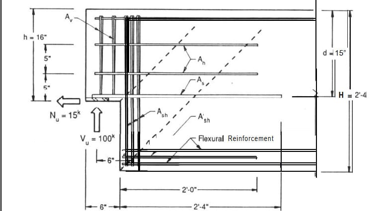
I'm referring to the weld detail typically used on corbels in which the tension steel is welded to a horizontal anchor bars or bearing plates, such as the detail shown below.
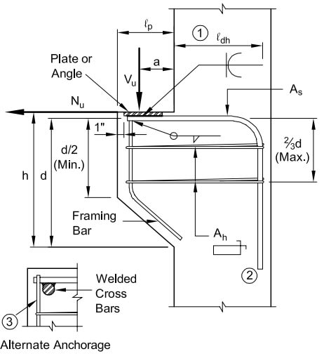
Corbel_hiojyb.jpg


I'm particularly interested in the detail shown below, when welding to bearing plates and/or embedded angles. I would imagine the plate would require some sort of shear connector to be effective when in this orientation, since I doubt there is much of a bond between the concrete and the plate to anchor the bar effectively. However, I haven't been able to find any example showing the sizing of such a part; the dapped beam design examples I've found so far typically skip the sizing of the bearing plate/angle.
Dapped_Beam_ok8cff.jpg


Opinions?
 
Replies continue below

Recommended for you

Our corbel details for bridge abutments to support approach slabs don't have bars terminating at the corner of the corbel. We use a single bar bent around as a stirrup, with both ends anchored into the abutment and a hook at the end of the top leg.

Your details would allow for the reinforcing to be slightly closer to the outside corner, but we use a corbel that is wide enough to get adequate bearing area accounting for the unreinforced corner. I suppose if you needed a bearing plate anyway, I can see going to the trouble of welding the bars to it. We would likely use automatically end-welded studs, attached in the shop, to anchor the bearing plate, to avoid field welding.
 
@HotRod10: I would like to check that detail out. Could you direct me to it?
 
@ HotRod10

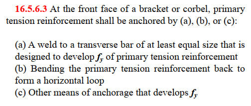
I'm not sure I'm a fan of that detail since ACI 318M-14 16.5.6.3 explicitly requires the bar to be developed by (a) a weld to a transverse bar, (b) the rebar bent in a horizontal loop, or (c) some other means of anchorage that develops fy.

Desktop_190418_0805_ic9mrs.jpg


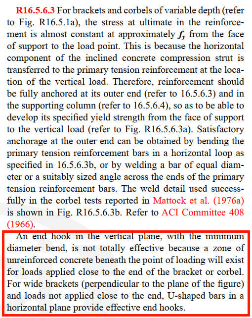
The commentary, in particular, advises against vertical hooks/bends.

Desktop_190418_0807_abyeep.jpg


With enough reinforcement to use the Asreq/Asprov provisions, the development length might me reduced enough for that to work on a bridge, but I'd be hesitant to use it somewhere else, since I don't think there is enough space to develop the bars such that they are fully developed at the point of load application. Then again, curved bar nodes might provide an alternate mechanism to develop those bars.
 
The top leg of the bar is developed with a hook, and then some (hook development length for a #5 bar is met, and 1' - 3" is more than twice the standard hook length). The bottom leg is in compression and adequately extended for shear. Several decades of use by us and numerous other states prove that it works for the loading from highway trucks (28 kip design point load).
 
Do keep in mind that the corbel is not dimensioned in that drawing, so perhaps my sense of scale might be off.

With all due respect, hook development for a #5 (at least based on the ACI equations) is not met (at least, not without going into curved bar nodes and the likes).

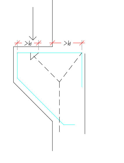
If a strut and tie diagram is superimposed on top of the stirrup in the detail you linked(see the very crude sketch below), the hook development length must fit between the edge of the corbel and the end of the nodal zone. Assuming that the reaction is somewhere in the middle of the corbel, there isn't that much space to develop the bar.

Desktop_190422_1326_gzg6sq.jpg


My question concerns the fact that, by bending the bar in a horizontal loop or welding it to an anchor bar/bearing plate, the code prescriptively states that that bar anchorage is satisfied, yet I've been unable to find further guidance on the topic. Since my application is not strictly a corbel (dapped beam + beam ledge), I don't want to apply this provision to a different use case blindly. Is there any good document/paper concerning the development length of bars anchored in this fashion? I'm fairly sure I'm probably overthinking it, but I'd rather be certain that I'm not missing anything.

Then again, (and as you state), the detail clearly works since it has been used repetitively. My guess it that the bar bend at the ends acts as a curved bar node, but I defer to anyone more experienced in the subject.
 
If the stirrup was the only reinforcing, I might agree with you about it not being developed (I'd have to check my AASHTO spec, but I think 8" is at least close the the full hook development length for a #5, 60ksi bar). However, there are 3 horizontal ties around each stirrup and horizontal and vertical reinforcing layers in the rear face of the abutment, that the stirrup and ties extend beyond. While that is not explicitly accounted for in the calculated hook development length, in reality, it has to make a difference. We haven't gotten into designing by the strut and tie method much yet, but I believe the the 3 horizontal ties change the modeling, don't they?
 
Status
Not open for further replies.

Part and Inventory Search

Sponsor