Eng-Tips is the largest engineering community on the Internet

Intelligent Work Forums for Engineering Professionals

Angled wood stud capacities 1

Status
Not open for further replies.

Jmeng1026

Structural
Jun 11, 2018
52
0
0
US
I prepared a set of plans for a deck and the client and contractor change things during construction.

Attached is a picture.

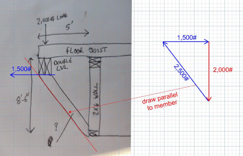
Instead of cantilevering the floor joist out two feet they cantilevered them out 5 ft and now want to add live loads.

Therefore a double LVL beam will be installed at the end of the cantilever.

Each end of the LVL beam will have about a 2000 lb point load.

Due to the site slope the contractor would like to install angled support members instead of straight up and down members.

How can I determine what size and how many plies the angle support member needs to be? Are there tables that show the structural capacities of angled support members or what formulas would I use?

Thank you for the help.
 
 https://files.engineering.com/getfile.aspx?folder=b5b445c9-8df0-4960-a652-91a3669e9b5b&file=16826859693752612521955489012790.jpg
Replies continue below

Recommended for you

1) What kind of LVL are you specifying? 98% of LVLs will rot in this application. Only one manufacturer makes a treated LVL, and they're on the west coast. I'm in Coastal VA, and they haven't made it to my market yet. I doubt they're in NY, but maybe. If treated lumber won't do it, you'll either need a treated glulam or a treated PSL.

2) This is pretty basic statics and mechanics of materials. Do an analysis to determine the axial load in the member, the moment in the member, and the shear. Size it the way you would any other wood member. (Hint: you'll need trig.)
 
I may not come up with a plan for them due to my minimal experience with angled supports but I would like to learn how to do it. Thought I would check on here to see if someone could provide some guidance.
 
As long as the connections are pinned (which is a pretty good assumption given the construction methods), it's simple vector math. You do know how to combine and separate vectors, right?
 
The compression in the diagonal member looks to be about 2,500# (see graphical solution below).

You have a problem at both ends of the diagonal, one mentioned above by SWComposites. But there is another problem at the top, The horizontal force is about 1,500# and will tend to rotate the double LVL clockwise, so you need to come up with a suitable connection there as well.

And as stated above, make sure you specify a suitable preservative treatment.

Capture_tzeazg.jpg
 
Did a similar detail last year, but I used C6's on the diagonals and HSS columns in the wall (my supports didn't go down to the base like this one).

To get it to work in wood is tricky as everyone mentioned above, but the analysis is pretty straightforward. I didn't know you needed experience in angled supports. It's not like this is dynamic analysis, it's the same as any other design, just slightly tilted. You're making me nervous.

Wouldn't it just be easier to double up the floor joists?
 
Beefing up the joists so they can cantilever 5' may be another possibility if the existing wall and foundation are adequate. Then there would be no need for the double LVL beam.

Alternatively, the LVL beam could be moved in 2' and supported on vertical posts down to a new footing at each end, but the contractor has already considered and rejected that idea due to a sloping site.
 
If the question is how to determine the force in the diagonal, as has already been stated it is a straightforward vector math problem. If you have a genuine interest in how the force is derived (as opposed to just wanting someone to give you the answer), there are plenty of online resources you can search up to guide you in the educational process.

My perception based on your original post is that you are in a pinch on the original plans for which you are now solely responsible, and you’ve been presented with a curveball that is beyond your ability to reliably resolve. For your sake and that of whoever will be occupying this deck, you should tread lightly. If you don’t have a grasp on this stuff you really should retain a duly licensed design professional to see this work through to completion. The details of the solution go far beyond deriving the size of the diagonal support member.
 
Status
Not open for further replies.
Back
Top