random_guy
Mechanical
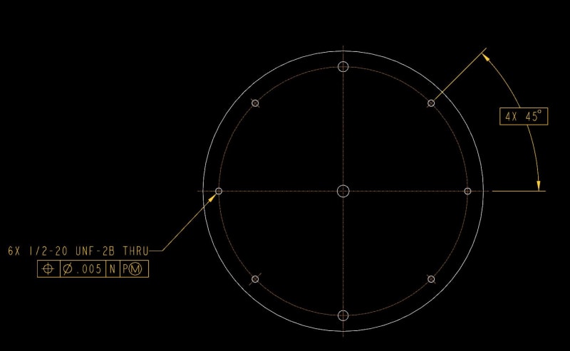
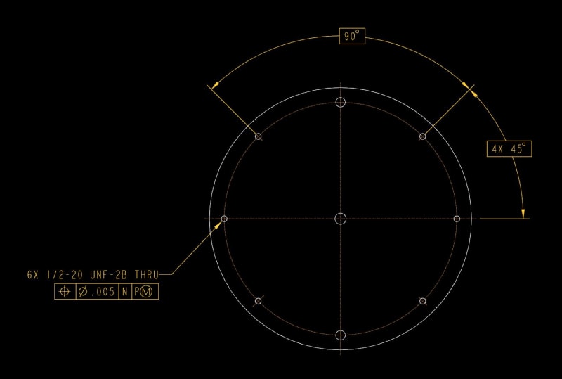
There are 6 holes in the pattern in question (notice the vertical holes are a different size). The 6 holes are all controlled by the same FCF.
I have applied a 4X 45° callout to the holes. A coworker believes there needs to be a 90° basic dim connecting the two groups. I think it's implied 90°/180° from the centerline. This is a complex part (obviously not the same part shown), and the drawing is already crowded, so I'd like to omit the 90°. I believe this is covered under 1.4(i) and 2.1.1.3 (2009).
I did not find any similar examples in Y14.5. I'm wondering what everyone's 2 cents is on this. It's silly because the intent is clear in both instances, but in the interest of "correctness", I'm genuinely curious.
Wise men learn more from fools, than fools do from the wise.