Eng-Tips is the largest engineering community on the Internet

Intelligent Work Forums for Engineering Professionals

angular tolerance in ISO 2768-1 for sheet metal process 1

Status
Not open for further replies.

kokerkov

Mechanical
Sep 20, 2023
10
0
0
CN
Background:

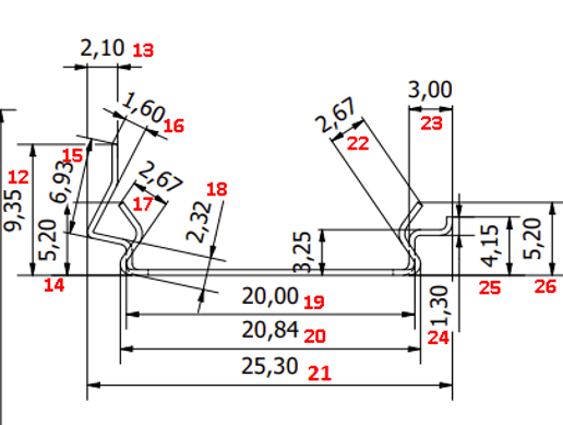
We are a Chinese manufacturer that got an order of an EU client. They made a messed-up drawing, saying all tolerances as per ISO 2768-1, and need to inspect all dimensions(seems like they measured all dimensions from 3D model)
20240111155417_gywbzn.png


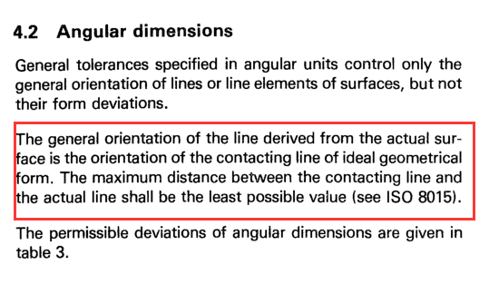
I already found angular tolerances(god, posts on the Internet about this seldomly mention it is decided by the short side of an angle), but ISO 2768-1 description about angular tolerances is strange to me:


The general orientation of the line derived from the actual sur-
face is the orientation of the contacting line of ideal geometrical
form. The maximum distance between the contacting line and
the actual line shall be the least possible value (see ISO 8015).
"


Sounds it is describing a tolerance zone as in GD&T/GPS system.

Can someone kindly explain to me how it is measured? Thanks in advance!

Plus: How can I talk to them to let them improve their drawing and requirement? Our technician told me this is not the way of doing things. Usually, people will only care about critical dimensions.
 
Replies continue below

Recommended for you

The dimensioning is odd, but it is almost complete and doesn't appear redundant, so they could all be inspected. It should include bend radii. It's also not typical to have dimensions to the sharp edges of sheet metal.

What appears to be missing is the tolerance class, which tells which group of tolerances apply.

As far as I know ISO 2768-1 exists only because there are companies who refuse to use geometric symbols and datum references. It's not a particularly good system.

---

All dimensions have the capacity to become critical dimensions if the features vary far enough from what is expected.

The usual is to look at the typical variation of the manufacturing process that is used, where what is typical is per factory, and see if the tolerances that are applied are much smaller than the design tolerances allow and assume that, after it is known the factory is making parts with the variation centered in the allowed tolerance, to only look at those features where the factory is less capable.

For example: If material is cut to length and the variation is +/-20 mm but the length is 10,000 mm and the allowable tolerance is 100 mm, then, after the initial setup and trials have shown parts are produced from 99,980 to 10,020 mm then inspection may relax. But if a part is made to 9,000 mm then that would become critical.

 
3DDave said:
As far as I know ISO 2768-1 exists only because there are companies who refuse to use geometric symbols and datum references. It's not a particularly good system.
I agree with that.
As a matter of fact ISO22081:2021 replace ISO2768-2 (This first edition cancels and replaces ISO 2768-2:1989, which has been technically revised.).
Again, I know we are talking about the "-1", but my point is that half of "the system" 3dDave is talking about is canceled and replaced.

One way out COULD be to ask the customer to proove that whatever you produced will impaire the functionality of the product.
A4 paragraph ISO2768-1 could give you some legal bearings on this fight.
"Exceeding the general tolerance should lead to rejection of the workpiece only if the function is impaired". Ask them to demonstrate that the "as produced" parts impaire the functionality of the part. Then, maybe, you will find out which feature is "critical" and which is less critical.
But I agree with 3DDave: "All dimensions have the capacity to become critical dimensions if the features vary far enough from what is expect"
What means "far enough" for each feature?


Grade is "M" in ISO 2768-1

Can you explain this a little?
%E4%BC%81%E4%B8%9A%E5%BE%AE%E4%BF%A1%E6%88%AA%E5%9B%BE_17050201988382_aaqmkj.png


Why to use ISO 2768-1 is simple. They usually dont have such 'complicate' part, most of them are helical springs. So in most cases, ISO 2768-1 is enough. So they probably think it can cover all.
 
The rules of ISO 2768-1 are somewhat ambiguous. There's a whole standard on angular features of size - ISO 14405-3. From the section you've highlighted it seems like ISO 2768-1 is applying two-line angular size. Annex A of the standard provides more info this specific case. Unless they've invoked any ISO GPS standards (ISO 2768-1 is not one), then the definitions of ISO 14405-3 don't strictly apply but they can at least provide a guideline for you. In my opinion there's too much specification ambiguity in their drawing to resolve any edge cases. As is I'd consider 100% measurement on that drawing a waste because there's no defined rules. Perhaps you could talk to them about making a quality plan to work out the ground rules for what actually makes sense to measure for them to have an acceptable part.

Capture_ofnyey.png

Capture_c5uscf.png


Ryan.
 
Ryan6338 said:
The rules of ISO 2768-1 are somewhat ambiguous. There's a whole standard on angular features of size - ISO 14405-3. From the section you've highlighted it seems like ISO 2768-1 is applying two-line angular size. Annex A of the standard provides more info this specific case. Unless they've invoked any ISO GPS standards (ISO 2768-1 is not one), then the definitions of ISO 14405-3 don't strictly apply but they can at least provide a guideline for you. In my opinion there's too much specification ambiguity in their drawing to resolve any edge cases. As is I'd consider 100% measurement on that drawing a waste because there's no defined rules. Perhaps you could talk to them about making a quality plan to work out the ground rules for what actually makes sense to measure for them to have an acceptable part.

Thanks,sir. This is helpful.
 
Status
Not open for further replies.
Back
Top