Continue to Site

Eng-Tips is the largest engineering community on the Internet

Intelligent Work Forums for Engineering Professionals

  • Congratulations KootK on being selected by the Eng-Tips community for having the most helpful posts in the forums last week. Way to Go!

ANSI load tap changing transformers

Status
Not open for further replies.

kartracer087

Electrical
Apr 18, 2020
61
Hi,

I have a question regarding ANSI style load tap changers applied on the low voltage winding (26.4kV) windings for distribution transformers. I have seen series type LTC's applied to these units where the winding is split into a main winding and a tap winding. Typically ANSI spec tap changers are +/- 10% in 0.625% steps. Now let's say you have a transformer delta primary grounded wye secondary 138kV - 26.4Y/15.52kV. Figuring roughly 80 turns in secondary, 15.52kV rated, if your regulating winding is to get 0.625% how is this possible? 1 turn added or subtracted is 1/80 or 1.25%. And adding turns to the secondary winding to get close to .625% per turn added or removed is not a solution because that would increase the overall transformer impedance far too much. So how can you get the smaller steps in voltage when the LTC is directly on the LV? Does the reactor used in the load tap changers play a part in the reduction in volts per turn?
 
Replies continue below

Recommended for you

So maybe what happens is the main 80 turn winding feeds another series winding with 160 turns. Then another series winding with equal number of turns (160) and having taps on each turn is wound in the opposite direction of the first 160 turn winding. So if your takeoff point is 159/160 turns you would decrease voltage by 0.625%. To increase voltage the winding would be fed in reverse so the ratio 160/159, Is that how it could be done?
 
I am not very familiar with ANSI transformers.In US they use a mid tapped auto-preventive transformer for oltc ( frankly I don’t know where or how this term came for reactors). When they are working in mid tap you will get half the tap voltage ie 0.625 % in your case. Of course using a series transformer is another alternative ; but not economic and may not be required in this case.
 
As prc said, for reactive type OLTC (usual for US), you will have a tap winding of +/-8x1.25% as the preventive autotransformer can be connected mid tap providing half tap voltages, increasing the total number of tap positions to the standardized +/-16x0.625%.

So, in your example, the tap winding will in fact have 1 turn per regulation step.

See here the manufacturer explanation for the switching of a reactive type OLTC (Reinhausen RMV) on pages 18 and 19.

Hope it helps.
 
Thanks argotier, so it would be something like this image attached? So then the impact is you are getting a voltage divider circuit across the reactor by paralleling the two tapped turns giving the effect of a half turn?
 
 https://files.engineering.com/getfile.aspx?folder=23ba6cd9-c1a5-43e3-a3d0-1474167b40bf&file=auto-transformer.png
If it helps you to understand the switching sequence, yes it's something like that.

Just be aware that the OLTC actual circuit is not like your drawing, for instance the OLCT doesn't have one switch per tap, but instead two moving contacts and only one set of switchs per phase.

The two moving contacts can be connected to the same tap and then you will have the corresponding tap voltage (non-bridging position, as called in the document linked above) or can be connected on two adjacent taps, and you have now the mid-tap voltage (bridging position).
 
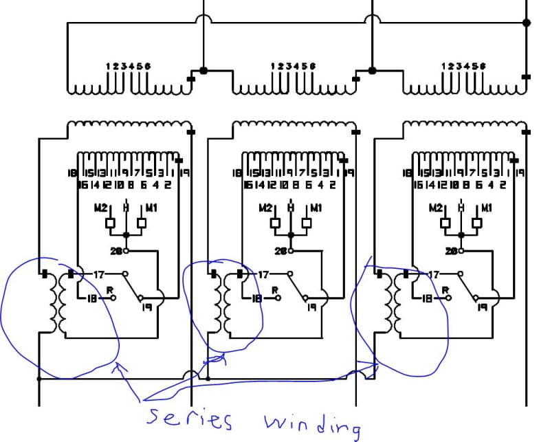
Transformers with low side LTCs sometimes have an additional series transformer. On this 115 kV/12.47 kV transformer I think the series transformer has about a 4:1 turns ratio. In addition to getting closer to 0.625% per step, this also reduces the current flowing through the LTC mechanism. Reduced current means smaller lead sizes though the tap board wall, as well as lower current through each moving contact in the LTC.
series_winding_ql2fwq.jpg
 
Series transformer is also useful to reduce the voltage to ground on tap-changer eg. EHV auto-transformers. Untill around 1965, 400/220kV and 220/132 kV auto-transformers were with such arrangement. But today line end tap changers are available for 220 & 132 kV application and series transformers are not used in such auto- transformers.
 
Thanks for the replies.

I wanted to clarify my second post I made on this thread. The issue with some designs is that to create the tap winding you are limited in the maximum number of turns you can provide to regulate. In my previous example, an 80 turn secondary winding would require a 1-turn regulating winding to achieve the 0.625% step in the bridging position. So, continuing on with that example and not having a series transformer, is it possible to have a tap winding with one layer wound counter clockwise then a second layer wound clockwise such that if I had 3 turns in the inner layer and 4 turns in the outer layer my net difference would be 1 turn? In this way it is possible to allow for more turns in each layer and still get the regulation step of 1 turn per tap. Simply making a single multi-start layer with one turn does not seem like it would be a preferable design. See my attached photo for what I mean, if this is something done or possible..

And yes, I agree series transformer adds a great deal of flexibility in the design, but may increase dimensions of the unit and add another point of failure. To me it seems like you would want to go to a series transformer where you cannot get an LTC that can handle the required regulating current.

Thanks.
 
 https://files.engineering.com/getfile.aspx?folder=2c8c6039-954d-42c0-aa21-b0e4246c3e26&file=IMG_20210121_112928786.jpg
Status
Not open for further replies.

Part and Inventory Search

Sponsor