Eng-Tips is the largest engineering community on the Internet

Intelligent Work Forums for Engineering Professionals

  • Congratulations waross on being selected by the Tek-Tips community for having the most helpful posts in the forums last week. Way to Go!

ANSYS Workbench - Spreader - Lifting simulation (Stress)

Status
Not open for further replies.

SukiLeinen

Mechanical
Oct 10, 2016
20
0
0
BA
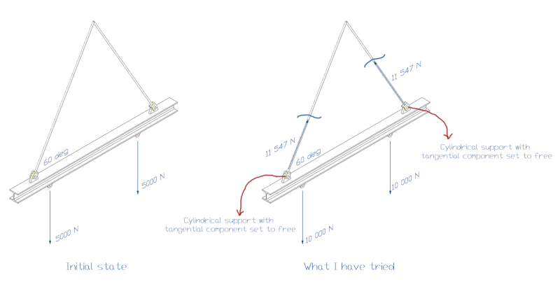
I have STEP model of simple spreader (I beam) with two lifting lugs for my home assigment. I want to simulate liffting of 2 ton load with my spreader. How to simulate lifting (lifting chains)in Ansys Workbench 16 only to transfer movment. What constraints to use. I don't need stress in lifting chains or lifting equipment, only in spreader and lifting lugs (When spreader is loaded with 2 ton load).

Thank You very much.
 
Replies continue below

Recommended for you

Any help would be appreciated. I have tried to decompose reactions in two lugs that I have on spreader. Lifting is done with lifting chains and angle betwean spreader and chain is 60 degrees. So in ANSYS I will apply two forces per lifting lug that are components of reaction force (reaction force in chain). But what type of support to use so ANSY can make simulation (so I don't have large deformation problem) - fixed support on one side of spreader and frictionles on another ? Will that be accurate simulation ?

Or to use cylindricat support with tangential component set to Free and apply it to internal surface of eaxh lifting lug opening ?
 
Would you share some more information on the actual arrangement of spreader beam to crane hook connection? Some pics of model? Direct or connection through again chains? Any way calls for direct constraining of the connection point of spreader appropriately. Apply the reactions of loads to be lifted directly as bearing load distributed over the connection area. But beware of Hertzian contact stress.


I have tried to do my analysis like this (as described in previous post).

spreader-example_iqzmti.jpg
 
Just see whether Ansys can solve your problem with four forces applied in the appropriate direction as per pic and fixing the 8 corner nodes of the beam in horizontal plane.


Hello Suki,

first, symmetrical half is sufficient. It also provides more stability. I would proceed as following:
1, model half of the loadspreader
2, fix the symmetry face all 6 DOF
3, Apply vertical load on the lower lug (10 kN)
4, Apply load in direction of the lifting chain (you know angle, you know the reaction force in chain)

your analysis should be in equilibrium so the fixed symmetry face should not give any significant reactions but provides stability to solution
If you use ANSYS Workbench you could use bearing load for force application as it gives proper distribution on the lugs.

Regards,
Pavel
 
Thank you NRP99 and Pavel Urubcik. Your help is much appreciated (I am novice at analysis and this is only practice) . Pavel, I am using ANSYS Workkbench. I case that I am lifting for example skid with 4 lifting lugs, and load is defined in equipments centers of gravity points , what would be your recomendation regarding supports in that case. Where to define support (constraints on model) so that analysis model is correct and reflecting "real life" stress state when skid is lifted.
 
It is difficult to imagine what is your actual model. I recommend reading something about symmetries generally applicable in structural problems. Symmetry usually helps you to reduce calculation time as well as constrain your model in more comfortable way.
 
Hello guys/girls,

here is what I have tried with skid mentioned in previous post.

skid-example_g6f6xi.jpg


I don't still know what is right approach when you want to simulate and calculate stress state in skid or spreader that is lifted in air and loaded. Maybe non of avaialble approaches are good.

How to find resultant forces in direction of fictive chains ? (I don't want to calculate them by hand because offten load is not in center of gravitiy of system - it is distributet asymmetrically and one lifting lug has bigger reaction forces then another)

Do I need to model chains ? Then are that chains elastic or rigid ? How to set them to be rigid ?
 
I have modelled chains in the past using springs elements with high stiffness (~1e8 N/mm).
You can split the lug inner surface so that the spring is attached only to one half.

As said before, to achieve a proper stress distribution in the lugs, bearing load can be used.
Maybe you can get the value and direction of the bearing load from the first analysis (with chains modelled as springs).
 
Do I need to model chains. I am not interested, as stated in stresss distribution in chains, only in skid. But I want to simulate thet stress state when skid is liffted. I only know distribution of loads (in center of gravity) on skid, not reactions. Lifting will be done by chains with angle od 45 degree, like shown in picture. I am interested in right boundry conditions on lugs inner surface. What sort of support to use. Only that. So I can have stress state in structure (skid) when it is lifted.
 
I don't know how advanced user you are so I will try to write in detail.

As mentioned in previous post: if the geometry and loading are symmetrical, you can model half/quarter of the model.

I would model either a chain or a bearing force on the lug inner surface. If you choose to use bearing force, you have to calculate it by hand. You
can create a local coordinate system in direction of the chain to define the load. Remember to split the lug inner surface so that the force or chain
is not acting on the whole surface.

If your load is not evenly distributed on the platform, I think you have to model the chains. In that case there is no symmetry either.

 
I am novice user. So thank you for Your time and patience. As I see it in my head, is it possible to simulate lifting and to get that reaction forces in each lug. How to support structure so that reaction forces are having direction same as chains. I hope I am describing reasonably :). How to get von-Misses stress, deformation and reaction forces.

If I replace chains with cicular bars that are overdimenisoned (for example 20 mm diameter) I will get reactions in them. But If I use for example cicular bars (40 mm) what effect will it have on my deformation and stress in structure. Will calculation it be valid regarding stress distribution and displacement values.

I tried to use remote displacement for this but I can not get reactions in the direction of the chain as they should be in reality. (Or x,y,z component - I don't know how to get them)
 
If the structure is supported by spring elements the reaction force resultant will be in the direction of the chain. I think for spring
you can only extract this resultant.

If remote displacement (one/lug) is used instead of spring element, you will get as many force reaction components as you have constrained.
If you set x=y=z=0, you will get three components. I would check that remote displacement results (deflections and stresses) correspond to spring results.
 
You do need to simulate the lifting chains with link element and following the general lifting rules.

1. The hook position should be located right above the skid weight center
2. The angle between the lifting chain and horizontal plane should be larger than 60 degree

You may need to provide lateral spring supports to the skid in the analysis model. Please note: the lateral spring support force shall be checked when the analysis is done. The analysis should be double check if there is significant forces in the spring.

Hope this help.
 
Gentlemen/Madams,

what do you think about modeling lifting chains as cylindrical bars and then assigning LINK 180 element to that four cylinders - with tension only propertie and then fixing them in common intersection point.

Problem is I don't know how to write that command. I know how to add it but I don't know correct syntax :/
I am using ANSYS Workbench as GUI not "pure" ANSYS APDL.
 
If you want to use link elements instead of combin14, check the following
link:
Also from Workbench help verification manual VM31. The basic procedure is to draw line bodies in
DM and then add a command object under each line body defining the element to be 180.

Can someone clarify why using link elements instead of spring elements in this case is a better option?
In my understanding, both have stiffness only in the axial direction so the results will be similar.
Using link elements requires a lot more work due to writing command objects and defining point-surface
contact to lug inner surface.
 
L__K, I was just suggesting that because I was reading some posts. To novice to completly understand. I dont know how to use Your approach. I am importing model in STEP file so I have also problems with defining line bodies in DM. But I am trying to figure it out (I am not modeling complete structure in DM). I was talking about LINK 180 because I have read that link that You have sen, before :)

What would be approach if I import my geometry in STEP format (Done in some 3d softvare for example). How can I then define COMBIN14 elements ? How can I draw line bodies (I will figure how to add command object). Or there is some other approach on this.

Thank You so much for information and patience. It is nice to have persons that are ready to help in this branch - very valuable infos.
 
After you have imported step and entered WB Mechanical, COMBIN14 (=spring with only axial stiffness) is defined under Contacts branch of the analysis tree. You can add "ground-body" spring where other end is fixed in space and other
end is the inner surface (or appropriate part of it) of the lifting lug. Springs elements do not require line bodies where as link
elements do.

To draw line bodies (in DesignModeller) you have many options. Either you can draw a sketch of line and then transform it to line body or you can create a line between two points. The basic setting for is that line bodies are meshed with BEAM188 elements. This is why, if you would use link
elements, should create a command object.

I am sure you will find a tutorial how to create spring elements in WB Mechanical somewhere.
 
Status
Not open for further replies.
Back
Top