Continue to Site

Eng-Tips is the largest engineering community on the Internet

Intelligent Work Forums for Engineering Professionals

  • Congratulations waross on being selected by the Eng-Tips community for having the most helpful posts in the forums last week. Way to Go!

Anti-sag Rod Design for either Roof or Wall Purlins 2

Status
Not open for further replies.

Neocheung

Structural
Feb 23, 2018
2
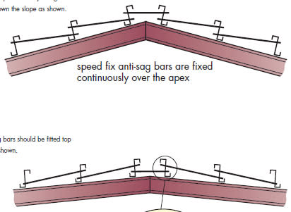
Does any one could tell me the difference between these two rod arranging patterns in the following picture? When should the first pattern be used and when should the second pattern be used?

Many thanks in advance.

2018-02-23_172514_ym4sfp.jpg
 
Replies continue below

Recommended for you

Sag rods are not the preferred way of bridging between purlins, but of the two options, the top one is best. This method provides a degree of stability against the tendency of the purlins to lay over down the slope.
 
Hokeie,

Isn't the failure mode you referenced up the slope not down the slope? Well, depending on the slope of the roof. This is the failure mode I have seen with roof purlins in the past. The attached photo (which isn't great) is of a roof purlin that has begun to fail by rolling over towards the ridge.
 
 http://files.engineering.com/getfile.aspx?folder=0f29a5e9-9344-4165-8302-b7d8152568e8&file=0303051123.jpg
The top sketch would be best if the net anchorage force is pushing the purlin top flange downhill. This would normally be the case on a steeper pitch roof.
The lower sketch would be best if the net anchorage force is pushing the purlin top flange uphill. This would normally be the case on a lower pitch roof.
Net anchorage force is going to be the directional sum of the rotational forces due to the purlin shape,which will generally push the cross-section towards the upper flange (function of the forces and the angle of the principal axis of the section), and the gravity component of the force which is always going to push the purlin downslope. For a 0 slope roof, rotational force is at a maximum and gravity force is zero. For a steeper pitch roof, the rotational force is smaller, and the gravity force is larger. Rotating the purlin to have the top flange facing the other way is not recommended for anything but minimal slope roofs, but will then make the two components additive and both would be oriented downslope.
 
SteelPE,

Yes, I have read some similar points like yours. Actually this picture was taken from a cold roll-reforming company's catalog. In this catalog, it is said that the zed purlin tries to roll backwards when the roof slope is bigger than 10°, while in other cases it tries to roll forward. I couldn't understand how did he get this conclusion because only the first arrangement is konwn to me in practice.
Also, the most popular point I have read is that when the first arrangement is used, the anti-sag rod would prevent the zed purlin from torsion under wind suction. But how about for the second arrangement? Can it work as lateral support in the same way?
 
Thanks, ajh1, for answering SteelPE's query about my post. I have never experienced a purlin rotating uphill, but per your post and his, it can happen.

Are sag rods commonly used? Not in Australia, we always use purposely designed bridging which braces both top and bottom.
 
Some manufacturers are probably using sag rods, although I suspect the majority are using small angles only in the top position, For Florida with the uplift conditions, bottom flange braces would also be necessary. If both top and bottom braces are present a single X or a connector plate to lock the top and bottom rows together would replace the diagonal sags. Many are now taking advantage of the AISI Spec provisions to do base tests where they establish a reduced capacity of the purlin without braces and restrained only by the paneling.
I work for BlueScope (Butler and VP brands) and we utilize a 5" deep channel to cover both flange requirements.
As noted for slopes under around 1.5-2:12 the rotational forces are larger than the gravity force component and the purlins will roll uphill.
 
No, we developed a drop-in pin arrangement. The channel flanges are extended as a tab that fits through the purlin web and are then pin attached to the next channel in line. Quick and easy with no tool involved. Channels for girts do require some sort of retainer on the pin to keep it in place since gravity doesn't work well horizontally.
 
Do you have a picture or brochure of that bridging system?
 
Status
Not open for further replies.

Part and Inventory Search

Sponsor