Eng-Tips is the largest engineering community on the Internet

Intelligent Work Forums for Engineering Professionals

Any ideas about this oddity?

Status
Not open for further replies.

itsmoked

Electrical
Feb 18, 2005
19,114
0
0
US
I have this little control transformer I've used for years to provide me with 230, or 460V for testing or powering controls I've built.

20160911_211559_ydv1ti.jpg


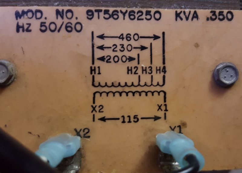
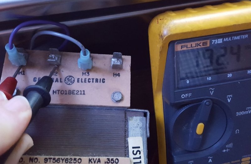
For the first time I need it for 208V. So I fed it 115.0V and checked the 200V tap and found it only had 186V. I brought it home and plugged it into 120.0V +5.0 more and.... all I get is:

20160911_211725_fyplb1.jpg


Is this reasonable?


Keith Cress
kcress -
 
Replies continue below

Recommended for you

Doesn't seem to be that far off. They're not typically precision devices. Good enough for Go/NoGo testing, but not 'Acceptance Testing'.

You should have a Variac variable transformer to adjust AC voltages to meet a precise spec for testing. I've got a half dozen because they keep showing up at flea markets for $5.


The turns ratio may be high to compensate for voltage drop. If that is the case, Then the turns ratio will be low when back feeding the transformer. That will result in low voltages.
Just for fun, try putting 240 Volts into the 230 Volt input and check the voltages at the 115 Volt and the 200 Volt connections.
I'm guessing about 208 Volts at the 200 Volt tap.
115 Volts x 240/230 Volts = 120 Volts plus 2% turns ratio error = 122 Volts at the 115 Volt output..

Bill
--------------------
"Why not the best?"
Jimmy Carter
 
The only thing I can contribute is that for large transformers on TTR test we expect the output voltage under open circuit condition to be pretty darned close to turns ratio times input voltage (closer than 1%).

Brainstorming what might be different about your situation:
1 - small transformers (0.35kva) act different than large (>5MVA)? Maybe higher p.u. leakage reactance and lower p.u. magnetizing reactance.
2 - lv leakage reactance higher than hv leakage reactance? (you're supplying magnetization thru low side vs TTR set typically on high side).
3 - measurement accuracy? Did you confirm 115V and 120V at the LV terminals during the test.

I've never played with small transformers but my guess would be #1 for what little it's worth.


=====================================
(2B)+(2B)' ?
 
This is isn't the first time I've run into the "suggestion" that small transformers aren't nameplated with true ratio so that they will come closer to producing the correct voltage with some load. Instead of full windings being 4:1, it might be 3.9:1 or some such. That would 118V out with 460V in.

What do you have on the H1-H3 terminals while you're making your measurement? If that's loading the transformer it could be compounding the problem.
 
And the rest of the story.----
Gunnar said:
The Squariac* is a transformer with multiple taps that are switched with relays that are closing on voltage zero and opening at current zero for "unlimited" relay life and zero arcing and interference. We have used a transformer with ternary windings for good resolution and a minimum of relays.

*That's what we call it to distinguish it from a Variac, which is round.

Bill
--------------------
"Why not the best?"
Jimmy Carter
 
Control Power Transformers are designed to provide optimum voltage stability as step-down transformers so that the inrush of solenoid coils does not affect the steady state voltage stability as much as it might on a standard distribution transformer. One way they do this is by very carefully designing the way the primary and secondary coils are wound around the core and each other. Instead of being more side-by-side on the core, the secondary (LV) windings are typically in close to the core and the primary (HV) are wound on top of them. The result is that they don't step-up as well as a standard distribution transformer might, the relatively high magnetizing current on the LV side causes a voltage drop on the HV (output) side.


"You measure the size of the accomplishment by the obstacles you had to overcome to reach your goals" -- Booker T. Washington
 
lionel said:
This is isn't the first time I've run into the "suggestion" that small transformers aren't nameplated with true ratio so that they will come closer to producing the correct voltage with some load.
I think you're onto something there.
GE said:
Compensated Windings
Voltage drop across transformers increases with load. At no-load a transformer’s primary : secondary voltage ratio may exactly match the winding turns ratio. At full-load the same transformer’s secondary voltage could be 3- 4% less than the turns ratio would dictate. The transformer winding turns ratio can be compensated to correct for this phenomenon. Smaller (less than 3 KVA) transformers commonly have compensated windings. Some manufacturers also build larger transformers with compensated windings. Winding turns ratios are compensated so that a 3-4% over-voltage exists at no-load, but nominal secondary voltage is available at full load.
So if the transformer is set up to provide a higher-than-nameplate no-load "output" voltage (for nameplate input) when we define in/out = hv/lv, then it will provide a lower-then-nameplate no-load "output" voltage when we reverse it to operate as in/out = lv/hv.


=====================================
(2B)+(2B)' ?
 
Ah good stuff here. Thanks folks! Never crossed my mind I was "running it backwards" since that was always my usage.

I'll run it "forward" and tell you what happens. Bill et al.

Pete; Thanks. Yeah, I checked the input 115V and 120V maybe a second before reading the outputs I reported.

David; Hi, I had nothing on those outputs when I did the above. I meant to point that out because it would certainly have made a notable difference. I'm using it to run a panel while I make the big clacky things rattle and freak my dog out with a PLC, but during the test the disconnect was open.

Gunnar; A Squariac?! Now I've heard everything. For a while there was a bench-top power supply company that made a standard lab supply that worked with only a linear regulator. As you turned up the output voltage you could hear it changing transformer taps. I thought that was really clever.

I have two Variacs but one is enormous and completely unenclosed making it scary to use and relegated to last resorts. The other is nice but weighs about 30 lbs and is a huge box with a cord that's an 1" in diameter so I tend not to drag it out either. I really should find a petite desk model for issues like this.

Thanks Jeff for the technical. I've always kind of thought about transformers as the simple thing sold to us in school. I need to keep these non linear details in mind.


Keith Cress
kcress -
 
Sorry for acknowledging Lionel but not Bill for his/their insight.
(Bill's comments didn't register with me the first time I skimmed them)


=====================================
(2B)+(2B)' ?
 
I didn't even reply electricpete.

All the small control transformers we use produce a higher no-load voltage then their nameplate would suggest. For a 600:120 transformer, instead of actually getting a 5:1 voltage ratio it's more like a 4.8:1 or 4.7:1 voltage ratio.

This is why you don't use a control power transformer for relays or voltage meters. You use a potential transformer.

 
Status
Not open for further replies.
Back
Top