This is a good question to the process engineer to answer with a detail control scheme and logic.
It looks that this is a primary flow control system with both variables of pressure and level adjustment to it.
The primary flow control is coming from FIT 0281 acting on valve FV-0281
All the other inputs from wherever they are are somehow calculating what the flow set point needs to be.
without the P&ID and a process description that's about all anyone can say.
Not quite sure what reverse action means, but could indicate that the set point is a minimum flow and hence if the flow is higher than the set point then the controller doesn't react, only if it falls below the minimum then the valve opens more?
Remember - More details = better answers
Also: If you get a response it's polite to respond to it.
This is how I read it. I could be wrong. Its difficult without more process info.
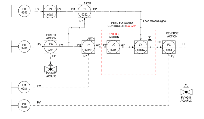
The primary pressure control is coming from PIT 0281 acting on valve PV-0281. An increasing signal from PIT-0281 Opens PV-0281. The PV is input into the two Arithmetic blocks.
FY-0282 Compares flow FI-0282 with pressure and calculates a predictor, or look ahead indicator signal
LY-0281B compares pressure with level indicator LIT-0281, calculates signal going to Level controller LC-0281. "Reverse" means LC's output decreases with increasing input, or increases with decreasing input.
LY-0281A converts electric signal to pneumatic signal, which is summed and sent to the flow controller FC-0281 as a Setpoint.
FC-0281 compares current flow with its Setpoint and moves FV-0281 into position. Valve movement will be opposite to FIT-0281's input signal, increasing signal closes the valve.
So, it appears to be controlling pressure immediately in the instant and adjusting flow in attempt to lessen the magnitude of the next pressure adjustment.
Its up to you to ensure the above logic makes sense to the process.
We can't tell what's happening in the Arth blocks, but it seems to amount to adjusting pressure, working out what the process needs in terms of flow and level, perhaps calculating a fill rate to a certain level within a certain time, and finally adjusting flow to make that fill target rate.
But yes, thats my imagination hard at work there.
I see it as a way of showing cascade PID controller configured the way 1503-44 tells it. An example is fuel supply to a burner. The fast loop controls flow to the burner and a slower loop supplys a SP for the flow controller based on temperature of the water heated in the boiler. Its not this LOOP but contains the same elements.