Continue to Site

Eng-Tips is the largest engineering community on the Internet

Intelligent Work Forums for Engineering Professionals

  • Congratulations SDETERS on being selected by the Eng-Tips community for having the most helpful posts in the forums last week. Way to Go!

Anyone Familiar with Hydraulic Spool Valve Pressure Regulators? 1

Status
Not open for further replies.

EnginerdNate

Aerospace
Feb 4, 2019
84
Hi All,

I've been handed my company's ancient static test system to keep running for the foreseeable future. The core to this system is an Edison Hydraulic Load Maintainer, which utilizes a combination of a balance beam, spool valves, and dash pots to regulate hydraulic pressures. Unfortunately the company is no longer with us so I'm on my own for figuring out how to get this thing working well. It's "worked" for our last few tests, but it's showing it's age.

The basic operation is simple, a bucket of lead shot is moved along a balance beam by a lead screw, and the other side of the balance beam is connected to the spool valves and a dash pot to damp the system. The system outputs hydraulic pressure proportional to the force applied to the spool valve by the balance beam/bucket of shot. The dash pots tune the response and keep the system from oscillating (They oscillate like mad if you turn the damping down too far or test a channel with the dash pot disconnected, ask me how I know!)

I do have the manual, and it has several adjustment procedures outlined and I've gone through and bled the system, made sure the dash pots had fresh oil, and flowed a few quarts of fresh hydraulic fluid through all of the channels.

On a few of the channels, when you first crack the valve open there is a big spike in pressure (2-3x the set pressure in some cases) then it settles down. These valves also show a good bit of oscillatory behavior as you change the set point. They do tend to settle down and provide the set pressure with time. I have tried increasing the damping on the dash pots following the adjustment procedure in the manual, but with little success.

I disassembled one of the spool valve assemblies and each spool valve core has 4x orings that seal each chamber to the block each valve body is inserted into in the machine. Could problems with these o-rings be contributing to any of this behavior? My other theory was that there was gunk build up on the exposed parts of the spool causing it to stick and then overshoot when it frees up, but I don't have any data at this point to back that theory up.

Any hints, reading suggestions, or tips welcome!

 
Replies continue below

Recommended for you

I think you're going to need to post a drawing, sketch, pictures and section to help us understand your issue. There's not much on the web about them....


Remember - More details = better answers
Also: If you get a response it's polite to respond to it.
 
The next time I'm in the office I'll try to get some scans of the manual illustrations. I had hoped that the spool valves were of a common enough design that some basic principles might apply to servicing/tuning them.
 
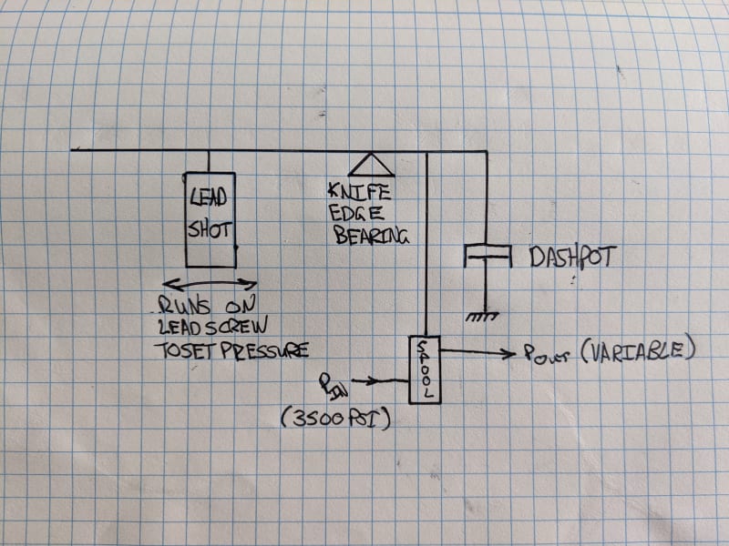
In the meantime, Here's a quick sketch of the setup:

PXL_20201030_144332952_wwmpbk.jpg
 
I found an old CAGE code listing with a phone number for Edison and called it. Got an answer and it was the owner, who was extremely helpful. Unfortunately the company lost everything in the Paradise CA Camp Fire a couple years back.

He stated that the oscillating behavior might be caused by some binding in the linkages connected to the oscillating system that keep the valves in a constant dynamic state to eliminate stiction (not shown in my diagram) and gave me some pointers on adjusting it.

He said the initial surge was a design issue they never overcame and that the best solution was to open the valves extremely slowly in the first few percent and to let everything settle at the ~5% load setting prior to moving up the scale.

Other than that he said that most undesirable behavior is caused by wear in the spools, which are not rebuildable and are now unobtainium since his remaining stock burned up in the fire, so I guess if anything fully lets go we're looking at purchasing a new servo controlled system from MTS or the like.

The bean counters will love that!
 
I'm guessing the 4 o'rings are used as dynamic seals to seal the moving spool? O'rings as dynamic seals have some problems - they tend to have a relatively heavy preload and they go from static (no relative motion between spool and rubber) to dynamic (relative motion between spool and rubber). So you have stiction versus friction changeover problems.
 
No they're static on the external mating surfaces where the valve body is inserted into the manifold. Thinking about it, it's likely that an o-ring problem would present as excessive leakage rather than any dynamic problem with the system.

The actual spool relies on two precision honed surfaces riding on an oil film to both maintain lubrication and provide the seal.

The oscillating system continuously rotates the spool about +-20* to keep the oil film working and in a dynamic friction condition to prevent that changeover.

So far none of the valves are showing signs of excessive leakage.
 
Oscillations are probably due to lag-time in response to a pressure change, thus the dashpot. The valve is too large and therefore can cause pressure to change must faster than the feedback response. A small "pulsation damper" would probably do a lot to reduce oscillations by reducing the rate of pressure change at the valve outlet.

Your drawing is missing a critical element. There is nothing that measures the pressure and provides feedback to the control element.

With a little initiative it seems rather simple to replace any part of this system with a new component that acts in a similar way to the old one. Some tuning may be required but you should not have to use identical parts.

Your drawing is very similar to how all pneumatic controllers work.
 
All of that happens inside the spool valve itself so it is difficult to draw. Pressure is set solely by the balance of force required to open the spool valve and the balance beam apparatus. The feedback signal is created by the pressure on the spool valve itself. It has a 'normally closed' behavior where the force required to hold it in a given position is proportional to the pressure it is outputting. This is all done inside the spool valve and I haven't diagrammed all of the parts/ports to understand how this is accomplished.

To calibrate, the apparatus is set to it's full scale, and the pressure adjusted by varying the amount of lead shot in the bucket. It is very primitive.

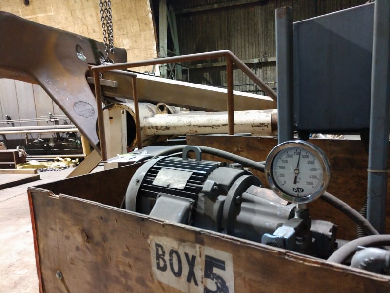
There is a pressure gauge on the output. This is used to monitor pressure and to aid in calibration, but there is no real feedback loop.

I pushed for us to move to a servo controlled system months ago (or abdicate our static testing responsibilities to an outside test house) but both options were shot down due to cost.
 
Compositepro,

You're spot on with the valves being oversized. The semi-retired tech who used to operate this machine happened to be in this morning and he confirmed my suspicion. The machine was originally setup with 10x 10,000 psi valves. One of them went bad and the only replacement part they could find was a 3,000 psi valve.

The channel with the 3000psi valve is easily the best behaved of the bunch, which makes sense as it is sized to regulate pressures up to a maximum of 3000 psi. On the other channels, I am trying to accurately regulate pressures from a few hundred psi to 2500psi or so maximum (some of my cylinders are only rated to 1200psi), so I'm using just a small fraction of the intended "full scale" on the valve. Just like any piece of precision equipment, the best performance is achieved by utilizing it in its proper range. I am only utilizing 1/4th or so of the range on 9 of the 10 channels.
 
I have a test fixture that uses a pressure regulator that has a hand knob so I can adjust the pressure when performing load tests.
In my case the area of the cylinders is known and we calculate the force based on the pressure.
Some thing you could add is a ball valve you can close and pre-set the pressure you want.
My set up is hard on the valve and creates a lot of heat, but I don't care because it is a short duration.

[URL unfurl="true"]https://res.cloudinary.com/engineering-com/image/upload/v1604329514/tips/Pressure_Regulator_zrp4nw.pdf[/url]
 
Yes, the biggest issue we face is that we need to simultaneously increment from 5-10% of load to 150% of load and on up to failure in 5 or 10 percent increments and we need to do so with multiple hydraulic channels in sync with different calibrations on each to get our shear/moment loading in the UUT correct.

Since speaking with the company owner last week, I expect that as long as I'm able to get a reasonable calibration up front and increment load slowly that I will be able to make the system functional for our immediate needs.
 
At times it can be a year or 2 between tests that are large enough to need the pressure gage only, any test under 100,000# we use a crane scale in the fixture, but when we do I just buy new gages that already have calibration certificates from McMaster-Carr.
One thing I do is to buy a gage with a range that puts my target reading about mid scale.
I'm told that is when a mechanical gage is most accurate.
 
Fortunately I have pressure transducers that I will be able to calibrate in labview to provide realtime feedback on all of the active hydraulics. In the occurence of an out of tolerance load condition or runaway cylinder pressure I'll be able to shut things down.
 
Status
Not open for further replies.

Part and Inventory Search

Sponsor