Eng-Tips is the largest engineering community on the Internet

Intelligent Work Forums for Engineering Professionals

Anyone here use Staad Pro Program to do Designs ? 1

Status
Not open for further replies.

-Daniel-

Structural
Jun 24, 2019
13
0
0
SG
I have one question about this program.
If i use this program to do RC design (say a 5 storey RC factory), some of the RC beams fail due to the shear problem, while look into the result, it failed due to the torsion moment on it. But in fact, while considering the floor RC slab can help to balance the torsion effect and real torsion effect won't be so critical. May I know, who do you deal with this problem? any setting can make it more realistic?


By the way, while applying a load on an RC floor Slab, what is the difference between a floor load and plate load? which one is more realistic? (From the result, there is some difference).

Many thanks.
 
Replies continue below

Recommended for you

In STAAD the plate load transfer is at each node so it is important that you have enough nodes along the beam and plate connection to represent a continuous connection. This may be the cause of your torsion.

Floor load is a method where STAAD allocates the applied area load to the beams based on the spacing. You can set this up several ways but I suggest using floor group method. Always double check the load is being applied correctly.

Plate loads are area loads applied to specific plate elements.

I have used STAAD for over 20 years and find it very useful however it is easy to make mistakes in the model and get incorrect results. Always step back and do a sanity check on the results.
 
thanks for your reply on the plate load, I think that is the answer, because i tried to apply more node, and the result is closed to the manual calculation result.

yes, I also used the floor load, but ....the torsion moment still happen. I have uploaded my concerned beam in the attachment, Can u kindly have a check?

(by the way, i used one way load for the floor load generation).

thanks
 
 https://files.engineering.com/getfile.aspx?folder=867a2662-da69-4820-becb-844771508c40&file=Document11.pdf
It is hard to tell from the PDF but it looks like you have a lot of constraints in a small area. I would suggest taking out the stair and doing that by hand. That may be inducing some unusual moments. Next look at your results for each load case and see which one is causing the trouble, this may lead to a misapplied load. It will also help in identifying which load to study.

If none if this works out and the model is accurate can you just add some extra rebar and make the beam pass?

It looks like all RC structure - I assume you have all fixed connection's?

You have pinned base connections on what look like fairly short columns. This may be the issue. In the real world the foundation will be more of a spring. You can model soil springs in STAAD. Alternatively change to stiff spring in translation directions and see if this helps. Depending on the severity you could just use very stiff spring which would be more representative of the actual situation.
 
thanks for your good reply .

actually, i also do a study to see if it is due to the staircase and pinned the beam end to release the moment, but the result is the same.

if there is one beam join to the concerned beam, i can understand where the torsion moment come out and it may be reasonable. But for this case, I don't think the torsion moment is reasonable, unless the slab element there will have a large deformation.

yes, all base I used pin for easy design of piling foundation, you are right, in the real case, it should be a fix or at least, it can take some moment. and I guess if i make the support to fixed condition, it can pass. but the foundation pile may be over-designed.
 
-Daniel- (Structural)(OP),

What makes you think the edge beam has no torsion?

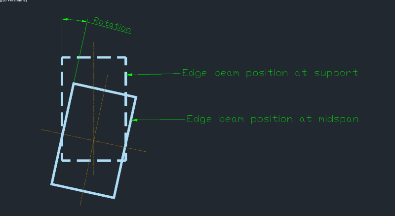
At the two supports the beam has no or minimum deflection. AT the mid span it deflection downward to carry the floor load. At the same time since one side is loaded but the other side has nothing so the beam at mid span must twist slightly and that is the torsion you have to design for.

If you list the deflected profile laterally at the mid span with the slab you should get information on how much the beam has rotated.
 
Some options to consider are below but you'll have to judge whether they're appropriate to your situation. You may already have done the first couple.

- Model the slab offset vertically from the beam centroid.

- Use cracked section stiffness instead of gross section properties. Torsion cracked stiffness is usually reduced more than flexural cracked stiffness.

- Use 'torsionless' design where you set the torsional stiffness to zero and provide a certain minimum amount of torsion reinforcement as set out in the design code.

- Rely on an increase in torsion strength provided by an integral slab. Staad is probably checking using isolated beam equations whereas a beam-and-slab is several time stronger in torsion.
 
Personally I don't understand why a designer wants to avoid the provision of torsional reinforcement.

edge_beam_rn3b4f.png


Physically the beam at the support from its original shape has been twisted when it reaches the midspan. The twisting action must happen because at midspan the underside of the edge beam must match the slab which rotates slightly at the edge but becomes perfectly horizontal somewhere near the middle. The above is an inescapable condition when a slab is supported on four sides.

Torsional reinforcement is most effective in a close loop so this is done by having a larger bar at the beam's 4 corners plus additional ties over and above what is required for shear.

If torsion is ignored and the edge beam later develops torsional cracks, which are easily identifiable, then the designer will be in trouble.
 
To: steveh49

Thanks for your reply,

May i know how to "offset slab vertically from the beam centroid"? I don't how to do it in Staad, I only know how to offset beam elements.

Actually, shy to say that i also not very sure how to do the below 3 method that you listed down in Staad pro. If you don't mind, can u teach me? Many thanks.
 
To saikee119

Sorry, Maybe i didn't explain my concern correctly as my English is poor.

Firstly I agree with you, torsion cannot be ignored if there is and it is significant. My question is because.... I don't think the result from My Staad pro model is correct. the reason is.... OK. assume there are two beam (same size) and one beam is quite long (say 11m) and another beam is shorter, (say 4m), while same udl load is applying on it, which one will have a bigger torsion moment? I believe the longer beam will have a bigger result. (Pls correct me if i am wrong). But from my result, you can refer to the pdf file i uploaded, along the beam, the one I arrowed is failed due to torsion (that beam is 1.7m only), but next to it, the longer beam (11m), it can pass (section size same). So it is quite strange, (and I checked with the deformation, the deformation on the long beam is much much bigger than the failed beam). But Mx moment (torsion) on the shorter beam is much bigger than the longer beam. I even not sure where does this extra torsion moment come from.

So i believe something is wrong. but i cannot really know where is the mistake i made. That's why i am trying to find a way to reduce the torsion effect on that short beam and see the result.

Many Thanks for your kind attention to my question.
 
It's good that you're trying to understand your analysis and results more fully before committing to a design. I can't help with Staad specifically, but I think you should try reducing the stiffness of your beams first. This will be the simplest change. I'm assuming your current analysis uses the gross section properties (I = bd^3/12 and J = bd^3/3). After cracking:

I.cracked ~ 0.4 * I.gross
J.cracked ~ 0.2 * J.gross

You should be able to create beam properties where you can input these parameters manually. You should also try to reduce the slab (plate) stiffness similarly but this may not be as simple. Compare the bending moments, shear forces, torsion moments, defections etc between the cracked analysis and your current analysis.

I suggest this given your comments about the short member having higher torsion. This could be because a twist is being imposed on the beam and it is stiff due to its short length, resulting in large torsion moment. This would be relieved by the lower stiffness in the cracked analysis.
 
Based on the diagram uploaded on 4 Jul 19 11:40 I believe Staadpro is correct.

The way I interpret the result would be as follow:

Along grid line 7 Bay c1-c3 has less line load (or udl along the beam width) than Bay c3-c8 so the rotation, along axis c3/c4/c5/c6/c7, is expected to be clockwise.

In fact the entire axis c3/c4/c5/c6/c7 would have been also clockwise if the bay enclosed by c1-c2-c4-c3 is absent. The torsion in that situation comes from the differential rotation. This is because in the model all supports were pinned and the base can rotate but fixed in x and y directions.

You can prove/see this by omitting Bay c1-c2-c4-c3, all short span beams c3-c8, c5-9, c6-c10 and c7-c11 making the entire c3-c7-c11-c8 “simply supported”. The torsion in beam c3/c4/c5/c6/c7 will be forced to zero due to the absence of any rotational restraint.

Once the stairwell bay has been added as per your design the edge beam at node c4 suddenly finds some heavy load on the opposite side forcing the beam to twist locally in the opposite direction. By inspection the rotation could move back to anticlockwise. At the very least node c4 could not possibly rotate in the similar manner as the rest of beam from c3/c4/c5/c6/c7.

Therefore the torsion in beam section c4-c5 is to be expected to be high if not the highest.
 
steveh49 (Structural)

Please do not take offence if I comment on your proposal. I do not doubt your idea could work in some cases but as far as I know all reinforced concrete codes do allow a concrete structure to be analysed using "gross" sections.

The above is good engineering practice and is universal.

The reason behind this is because in structural analysis it is the "RELATIVE" stiffness at each node that determine the distributions of forces, moments and shears. Many older engineers brought up to do manual calculations would not bother with the actual I-values of the gross section and used just their relative ratios in the "moment distribution method".

Therefore a selected local change to the gross section does not accurately reflect the true behaviour of the structural system and must be applied with caution and full justification.

 
I know many codes allow gross section properties to be used within certain limits appropriate to this simplification, so I would say it is acceptable practice in those circumstances. Gross properties wouldn't be appropriate for investigating slenderness effects in cracked structures, for example. I certainly wouldn't say the use of gross properties is universal as the codes I'm familiar with recommend using properties that reflect the degree of cracking.

I haven't used moment distribution myself so did a quick web search, opened the first half-dozen pages, and searched for 'torsion'. No mention in any of those pages so I wonder whether moment distribution is inherently torsionless design. Perhaps this is even the origin of code provisions for minimum torsion reinforcement - when analysis of compatibility torsion wasn't practical. Can anyone confirm or correct this speculation?

saikee119 said:
Therefore a selected local change to the gross section does not accurately reflect the true behaviour of the structural system and must be applied with caution and full justification.

Agreed. In this case, Daniel reports that the beam fails in torsion so is certainly cracked at the ultimate limit state. Uncracked stiffness is not the true behaviour, and I did recommend adjusting all members for cracking, not just the one that's failing. Another design option is from the FIB Textbook (Bulletin 52):

"Therefore if a combination of torsional stiffness and bending stiffness is of decisive
influence one should do a two-step analysis. For the serviceability state one should regard the
torsional stiffness of the uncracked cross section in order to get sufficient reinforcement to
reduce the crack-width. However for the analysis of the bearing capacity it is proposed to
neglect the torsional stiffness setting it zero in order to get a safe solution."

 
-Daniel- (Structural)(OP),

The following story was when I was first hit by torsion in RC design.

Over 40 years ago as a young engineer I was charged with the design of a massive 2m deep roof structure, to be simply supported on four massive walls, for the first UK nuclear fusion laboratory.

One day I was summoned by the chief engineer who expressed bollocks at my design for having a huge demand of torsional reinforcement. This is because in a flat slab design people do not need to put in any shear reinforcement let alone torsional steel but I had both.

One design requirement was the roof had to be demolished one day and so the structure was divided into 1m wide beams supported on the short span to facilitate demountability. There was uncertainty if the roof during service could be contaminated by radiation requiring the broken concrete specially removed and sealed. The radiation in nuclear fusion is known nowhere as harmful as in nuclear fission on which the bulk of nuclear power plants were based.

Longitudinally the roof was post-tensioned by tendons after the whole was cast in one operation with beams separated by profiled sheet metal. When the beams were finally de-tensioned in future each beam had to be able to stand on its own. Therefore shear reinforcement was required.

The unit metre beam, say Beam A, at the middle of the long span had its underside flat both at the support as well as at midspan. This beam section had no rotation and so no torsion.

However along the long span the unit metre beam, say Beam B, had the highest torsion next to the short support . This high torsion in Beam B would disappear if the post-tension were not applied and Beam B were allowed to drop down freely as Beam A at the mid span. The problem was if all beams were designed as Beam A then the roof could only be supported on two sides and not 4 sides due to the midspan deflection interfering with the two short supports. By applying the post-tension in the longitudinal direction Beam B was twisted so that its underside could rest on the support.

My chief engineer eventually accepted my design which was built and still is standing today.

Thus torsion can occur and a designer must understand why it happens and adjust the design accordingly.


steveh49 (Structural),

I now tell you another part of the above story relating to cracked section analysis.

The nuclear fusion laboratory roof was poured in one operation fully supported on temporary falsework. The spec required the falsework could only be removed after 28 days.

The contractor wanted to save money by removing a portions of supports early and progressively. This was agreed with the chief engineer upon the production of satisfactory cube strength (in USA people crush concrete cylinders instead of cubes).

I was then required to provide my predicted deflection profile of the roof for comparison when some supports were released. I lifted the result from the FE analysis based on the gross sections. In the old days I had to write my own plate bending FE software too tailored to suit the limited core memory of the firm's central computer.

The feedback from site was the deflected profile in the field was always nearly twice my theoretical prediction. As soon as I learned this I checked the beam section , calculated the neutral axis corresponding to the loading condition and found the cracked section’s second moment of area, with concrete in tension zone disregarded, to be less than half of the full gross section.

Therefore in service condition using cracked concrete sections will give realistic deflections.

The above remains the biggest mistake I made in my professional life. Since then I developed a strong interest in computerising various national RC design codes and algorithms to analyse RC sections of any shape with full knowledge of the material stresses and strains from elastic to breaking condition.

In reinforced concrete the neutral axis changes position in response to a given load and so the cracked section is not constant but load dependent. To apply cracked sections globally to a structure would require each member checked for its neutral position to update its section properties. After the analysis each member can have slightly different member forces so the whole process has to be repeated iteratively. If the structure is stable the designer will arrive at a converge solution. Such approach could be termed as linear-inelastic analysis with multiple runs by refining the cracked sections as opposed to the linear-elastic analysis using a just single run based on the gross sections.


With any torsion, you need to recognise the fundamental differences between torsion arising from equilibrium or compatibility. Two fundamentally different mechanisms and codes treat the analysis and design of equilibrium and compatibility torsion in quite different ways.

The compatibility torsion is a torsion resulting from maintaining compatibility within a structural system. The classic example given in most codes is a beam spanning between other beams. It's not truly pinned so some negative moment develops, this creates torsion in the supporting beams. Usually in codes provided you meet certain criteria like anchorage of longitudinal reinforcement and a minimum amount of torsional reinforcement you'll be allowed to analyse the structure with torsional stiffness set to zero and pinned ends. This simply recognises that you are allowing torsional cracking and the redistribution of the torsion into moments in adjacent members. The minimum level of torsional reinforcement ensures that any cracking is addressed at the serviceability limit state.

Equilibrium torsion is such that if the equilibrium of the system relies on the torsion being resisted then you must provide sufficient torsional reinforcement and detailing to support that torsion. This torsional reinforcement (both extra longitudinal and transverse reinforcement) is additional to the requirement for flexure and direct shear. The classic example given in codes is that of a beam cantilevering horizontally off another beam. If the supporting beam is not designed and detailed for the torsion the cantilever doesn't work (no equilibrium).

I would imagine your code would explain this and have provisions for dealing with the two types of torsion.

Any analysis should take into account the member stiffness at the level of loading. Often for simplicity codes let you basically use an average value for a given member, rather than needing to assess the effective stiffness at regular intervals along a member.
 
Status
Not open for further replies.
Back
Top