Navigation
Install the app
How to install the app on iOS
Follow along with the video below to see how to install our site as a web app on your home screen.
Note: This feature may not be available in some browsers.
More options
Style variation
-
Congratulations MintJulep on being selected by the Eng-Tips community for having the most helpful posts in the forums last week. Way to Go!
You are using an out of date browser. It may not display this or other websites correctly.
You should upgrade or use an alternative browser.
You should upgrade or use an alternative browser.
API 650 Roof Weight 3
- Thread starter tzh0044
- Start date
- Status
- Not open for further replies.
Nozzles and flanges could be included (similar to roof structure attached to the roof), but are usually neglected for simplicity. Quite often, details and weights are not known when the roof is designed. Usually, roof nozzles are not symmetrical around a tank, and that lack of symmetry is not addressed in the standard, either.
- Thread starter
- #3
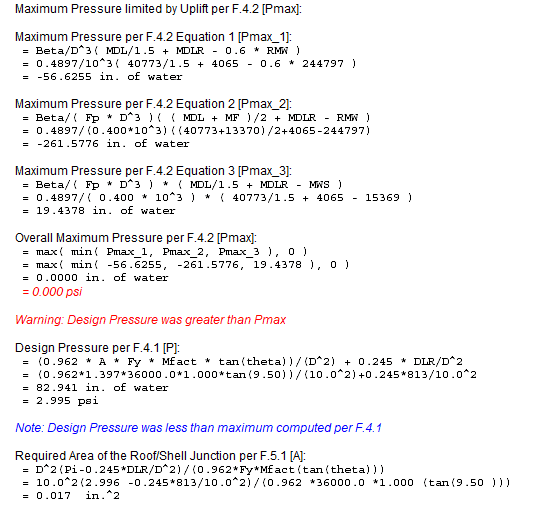
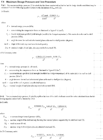
When working through Annex F.1-F.7, I calculated F.1 and F.4 by hand and got pretty similar number as my analysis software. But for the equations (1), (2), and (3) the software is taking the minimum of those, then the max of that of 0. So my design pressure is 0 psi, why is it doing that? My physical copy of API 650 doesnt have that step.


- Thread starter
- #4
JStephen, from your experience would you use the nozzle weights if you had an existing tank that you were trying to determine the MAWP for? Also I've been reading through API 650 today and when Ive needed a better understanding, your name has popped up on other threads. Thanks for all the help!
- Thread starter
- #6
- Thread starter
- #8
- Thread starter
- #10
-
1
- #11
- Thread starter
- #13
- Thread starter
- #15
-
1
- #16
It should be uplift by wind suction on the project roof area, an external force that produces overturning effect. I don't think internal pressure contributes to the moment. Anyway, the first term shall looks like "Roof Area*Pressure*Lever arm".
-
1
- #17
I missed the followup posts to this.
But one thing to note, that API has revised the wind uplift/pressure/overturning criteria seemingly with each addendum/edition.
So there is no assurance at all that a tank meeting the requirements of one edition will comply with the uplift requirements of a different edition.
Refer to API-653 to see whether the as-built standard or the current standard should be used for re-design/re-rate, etc.
HTURKAK
Structural
- Jul 22, 2017
- 3,368
Dear Tristin (Mechanical),
I missed this thread . Today morning looked to thread and responds. If your query still valid, will you pls share additional data ( steel material, anchors, content and (if any ) assessment data..).
I think the software that you use, checks the tank as per API 579 (Fitness-For-Service ) with assumption of PV. IMO , the tank should be checked as per API 653 Section 4.
- Thread starter
- #19
- Status
- Not open for further replies.
Similar threads
- Replies
- 6
- Views
- 4K
- Replies
- 4
- Views
- 824
- Replies
- 4
- Views
- 3K
- Replies
- 2
- Views
- 3K

