Continue to Site

Eng-Tips is the largest engineering community on the Internet

Intelligent Work Forums for Engineering Professionals

  • Congratulations GregLocock on being selected by the Eng-Tips community for having the most helpful posts in the forums last week. Way to Go!

API-653, technical reason for maximum size of welded on patch plate in critical zone? 4

Status
Not open for further replies.

Johns Hopkins

Mechanical
Apr 8, 2020
5
thread1452-419159

Hi,

I'm a quality assurance engineer at a manufacturing facility. My organization has acquired a neighboring chemical plant and I've been consulted about undertaking some possible repair work in a water tank installed there.
The historical reports of this equipment indicate that there has been some nonstandard repair work undertaken on its bottom plate in the recent past.
The details of this work are: an 84 inch long and 12 inch wide welded on patch plate was installed on top of a smaller insert plate within the critical zone.
API-653, Figure 9.13, dictates that the maximum length of the welded on patch plate should not exceed 24 inches along the shell. This nonstandard repair is in clear violation of the code; however, my question is: 'What would the consequence be, if I were to adopt this repair as a permanent one?' It has already been in service for the past 3 years, without the surfacing of any indication.
Is there any specific technical justification to API-653's limitation on the maximum size of welded on patch plate in the critical zone?

Regards,
J.H
 
Replies continue below

Recommended for you

Johns Hopkins (Mechanical) said:
.........an 84 inch long and 12 inch wide welded on patch plate was installed on top of a smaller insert plate within the critical zone.
API-653, Figure 9.13, dictates that the maximum length of the welded on patch plate should not exceed 24 inches along the shell. This nonstandard repair is in clear violation of the code; however, my question is: 'What would the consequence be, if I were to adopt this repair as a permanent one?'.........

Welded-on Patch Plates on Tank Bottom Plates are depicted on Figure 9-5 (API 653 2003 ) and see note 3. The maximum dimension along the shell for welded-on patch plates in the critical zone is 24 inches.

For the other places, allmost there is no size and shape restriction.

What is the type of foundation? (RC ring,Granular ring, RC pad..?) is there any risk for edge settlement?
 
I think JStephen's answer in the thread you linked may be the closest you'll get to a "technical justification".

I've always been reluctant to use "It has already been in service for the past 3 years ..." as a justification. I would suspect that a tank has not experienced it's full range of design criteria in such a short time frame. Things like the tank completely full in the winter with the weather at the Design Metal Temp, as well as whatever else this tank was designed for.

At some point it may be a judgement call by an experienced tank engineer. HTURKAK has some good questions. I would also wonder what size tank you're talking about (bigger tanks will have more stress in this area).
 
@HTURKAK and @Geoff13:

The type of foundation is RC ring and following are the remaining specifics of the tank:
Tank Diameter: 9330 mm
Tank Height: 7320 mm
Nominal Capacity: 500 m3
Service: De-ionized Water

The foundation is pretty solid, doesn't exhibit any nonuniform settling or irregular clearance of the projection plate. Furthermore, the previous internal inspection reports do not mention any anomaly in the dishing or bulging profile of the tank bottom.

Regards
 
Johns Hopkins (Mechanical)( said:
.........the details of this work are: an 84 inch long and 12 inch wide welded on patch plate was installed on top of a smaller insert plate within the critical zone...Tank Diameter: 9330 mm,Tank Height: 7320 mm....

The patch plates shall have a circular circumference at junction with shell. Will you post the details of patch ( and position, shape, welding to base and shell?

The minimum width of annular plate defined in API 650 La= 390 tb/((HG)**0.5). The theory behind this ,the thickness of the annular plate is a function of the stress and thickness of the first shell course ,and the width of the annular plate shall be adequate to support the weight of liquid content on top of it in the case of a foundation settlement with F.S.=2.0 . Another reason ,full plastic moment shall develop by yielding of the plate beneath the shell, that is, the annular plate shall not be stronger than first shell course.

Regarding the repair restriction 24 in ,in case of foundation settlement or distortion, the critical zone (so the patch) will experience high bending stresses which could tear apart the shell-to-bottom fillet welds.


Its a good question posted.

I have experienced too non-standard repairs owing to knowledge of the inspector and management present at that plant.
For instance:
- Patches with Corners not rounded.

Though the repairs were rectified after inspection by removing the plate and reinstalling as per API-653. But the history of original goof-up is not known. So it survived atleast 3years.
The committee regarding API-653 may shed a light into it. You may ask for elaboration for 24 inch bar and subsequently enlighten us as well.
But if possible, first thing would be to rectify this anomaly with replacement unless an engineering assessment is done.
Hope it may help to further move on this query.
 
Dear Johns Hopkins,

With due regards to all the replies above, do carry out MFL of the tank bottom before taking any decision about the tank. There could be severe underside corrosion, corrosion under coating etc. that could be detrimental. The last thing we want is a leak from the bottom plates.

Also, if the bottom plate and the shell are bare, think of some epoxy based coating that would increase the life of the water tank by years.

Regards.

DHURJATI SEN
Kolkata, India

 
@ Dhurjati Sen,

Records indicate that MFL was performed on the tank twice in the past. It was only on the basis of MFL that underside corrosion was detected and consequently addressed through this much needed, albeit nonstandard, repair.
 
@ HTURKAK

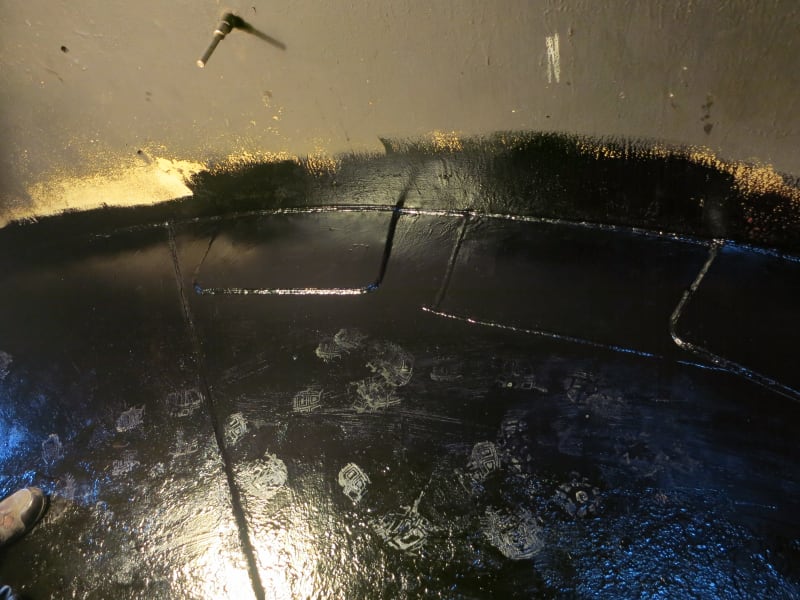
IMG_6584_hck07q.jpg


Following are the dimensions:

24 x 12" (welded on patch plate, on the left most part, installed in 2017)
29 x 13" (insert plate with nonstandard corners, in the middle, installed in 2014)
84 x 12" (welded on patch plate, on the right, installed in 2017 on top of the insert plate of 2014)
 
@ HTURKAK,

Regarding the foundation distortion or settlement, this equipment is not at risk of that happening. Any other reason why API-653's limitation might hold water in this case?
 
@ Johns Hopkins (Mechanical),

As per your explanation; magnetic flux leakage was performed twice in the past ; the tank is in service for the past 3 years and ; there is no risk of foundation settlement and distortion.

If the tank is not located at high seismic zone (in case of uplift the weldment may experience high bending stresses if the tank is not anchored) and the weldment (at shell-to-patch fillet weld ) free of cracks , personally i will agree with the repair.
 
The tank is small, and the product (water) isn't dangerous. I'd leave the 84" patch alone.

However, you said the MFL revealed underside corrosion, so slapping these patches on top doesn't fix your problem. They're only bandages for the symptom. It's such a tiny tank that next time I would take the full bottom out, replace the fill with a non-reactive one and install a new bottom.

Good luck.
 
Status
Not open for further replies.

Part and Inventory Search

Sponsor