FPPE
Mechanical
- Mar 4, 2022
- 194
Hi,
I'm designing a BEM heat exchanger with concentric cone and I have a doubt on evaluation of API 660 loads.
Design code is ASME VIII-1 2023 and equipment shall be marked with U designator.
Design conditions tube side: 1.77 MPa + FV @ 100 °C
Tube side MOC: SS316
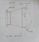
Please consider the following sketch:

As you can see, I have to consider API 660 values for external loads on nozzles.
I need the following clarification:
1) API loads are applied at the intersection of shell to nozzle junction. In this case we do not have a shell, but a girth flange connected to the extended portion of tubesheet.
This seems to be a case which should be evaluated only by FEA, but API loads should be applied on flange resulting critical than the ones applied at the junction as required by standard itself.
2) Gasket of flange-tubesheet joint is a GMGC kammprofile type and there are No. 36 (0.875"). Radial load on nozzle could be a problem for flange leakege?
Is there a way to consider those loads applied on flange by formulas for which we can avoid the FEA? Is it possible in software such us PV Elite?
Do you have any other advice for these design?
Thanks in advance
I'm designing a BEM heat exchanger with concentric cone and I have a doubt on evaluation of API 660 loads.
Design code is ASME VIII-1 2023 and equipment shall be marked with U designator.
Design conditions tube side: 1.77 MPa + FV @ 100 °C
Tube side MOC: SS316
Please consider the following sketch:
As you can see, I have to consider API 660 values for external loads on nozzles.
I need the following clarification:
1) API loads are applied at the intersection of shell to nozzle junction. In this case we do not have a shell, but a girth flange connected to the extended portion of tubesheet.
This seems to be a case which should be evaluated only by FEA, but API loads should be applied on flange resulting critical than the ones applied at the junction as required by standard itself.
2) Gasket of flange-tubesheet joint is a GMGC kammprofile type and there are No. 36 (0.875"). Radial load on nozzle could be a problem for flange leakege?
Is there a way to consider those loads applied on flange by formulas for which we can avoid the FEA? Is it possible in software such us PV Elite?
Do you have any other advice for these design?
Thanks in advance