Continue to Site

Eng-Tips is the largest engineering community on the Internet

Intelligent Work Forums for Engineering Professionals

  • Congratulations KootK on being selected by the Eng-Tips community for having the most helpful posts in the forums last week. Way to Go!

API 6A 21st Ed. Gate Valves design allowables 3

Status
Not open for further replies.

HansonBoye

Mechanical
Sep 26, 2019
17
Hi,

I am new to designing gate valves to API 6A 21st edition standard.
In the process of performing design calculation, I have few questions for which I am looking for answers.
1) When defining the design allowable stresses for pressure vessel calculation or wall thickness sizing, I am using API 6X method to calculate the design allowable stresses ie., 2/3*Sy for working pressure and 0.9*Sy for Test pressure conditions. But for the main calculation, i am following Von mises equivalent stress method or distortion energy theory method by combining triaxial stresses. Is it allowed to mix these two methods to arrive at equivalent stress?
2) How to calculate the allowable tensile stress? I have found through online resources that had .83*Sy to calculate maximum allowable tensile stress for body , bonnet, gate, seat, stem, and misc components. The calculation results were compared to this allowable tensile value to arrive at FoS.
I couldn't find anywhere that .83*Sy will give an allowable tensile value? is this correct or please let me know if otherwise.
3) Is it necessary to do compressive bearing stress calculation for seat to gate and seat to body interface for a valve with gate/stem that has a threaded connection? the reason i ask is when using a T-Nut style connection with a floating gate this becomes far more applicable, but not sure for a threaded connection.

Thanks.
Hanson
 
Replies continue below

Recommended for you

Hi,
1) As per API 6A 21st edition, you can use one or more than one calculation method to find out the results. but the method should be complete... you cant mixed two methods for single answer. since the conditions for each method is different. by API 6X formula, you can find out the max allowable stress intensity for design as well testing conditions. but the main calculation you should follow ASME Sec VIII Div 2 Appendix 4 : 2004 Edition with 2004 & 2005 addendum errata.

2) Reason to find out the allowable tensile??? since API 6A is completed related with yield strengths. St=0.83*Sy is to find out the max allowable general primary membrane stress intensity at hydrostatic test pressure based on the yield strength. so you can take the material yield strength from which material you have selected for the application, to find out the values. here Sy is the material-specified minimum yield strength.


Dinu...

There are no secrets to success. It is the result of preparation, hard work, and learning from failure.
 
Hi Dinu,

Thanks for your reply. It was useful.
I want to use the distortion energy method, that is by combining the triaxial stress to obtain the equivalent stress.
As in API 6A 21at edition the ASME method part has been removed and replaced by API 6X ie., earlier it was ASME Method to calculate allowables, 2/3 Sy and 5/6 Sy as per 20th edition. This was replaced by API 6X now.
Therefore, what are the allowable criteria for using the distortion energy method? is it still 2/3 Sy and 5/6 Sy ?

or as per distortion energy theory should i consider SE = SY ie., design factor of 1 times Sy instead of 2/3 Sy and 5/6 Sy?

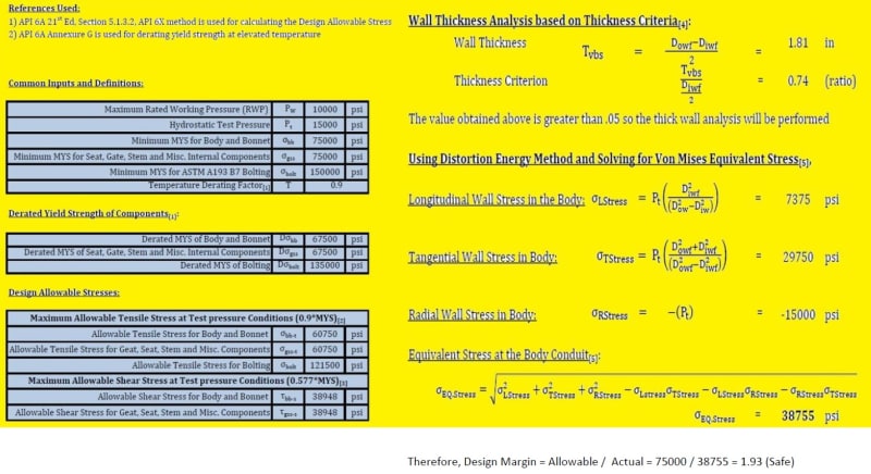
Attached is a sample calc i made using excel. Please can you check and let me know if its correct? Thank you very much.

Clarificatio_tjpdlc.jpg
 
Hi HansonBoye,

The following API 6A 21st Edition sections are applicable to your situation:

5.1.3.1: OECs, bodies and bonnets (in design other than those specified in this specification) shall be designed in accordance with one or more of the methods given in 5.1.3.2, 5.1.3.3, and 5.1.3.4.
This clarifies that you can use multiple methods to design a part (for example, use 5.1.3.3 for a straight cylindrical section and 5.1.3.2 for a discontinuity). It does not allow mixing of methods for one calculation.

5.1.3.2: If used, design calculations for pressure-containing equipment shall conform to the design methodology of API 6X. The use of von Mises equivalent stress shall be permitted.
Therefore, you can use von Mises stress for API 6X design (ASME method), based on the combination of this section and the allowance in API 6X 2nd Edition 5.2 to use von Mises equivalent stress instead of stress intensity when this is allowed by the product specification. The allowable stresses for this method are not SE = SY, but Sm = 2/3 Sy and St = 0.9 Sy, as stated in API 6X 2nd Edition 5.1.2

5.1.3.3
for basic pressure vessel wall sizing only (generally only straight cylindrical sections, not discontinuities or stress concentrations), von Mises may be used with SE = SY.
 
Hi Jmec,

Thank you very much for the details. Actually the question was to calculate for a valve body.

For straight uniform cylinders, I'm using only the principal stress formula below to calculate this.
vonn_ncjwxu.jpg


Where LStress - Longitudinal stress, TStress - Tangential and RStress - Radial stress.

and to arrive at a factor of safety, i use the API6A section 5.1.3.3 criteria for hydrostatic shell test condition, i.e., i would do use YS = 1 Sy

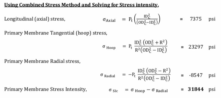
and for Non-uniform cylinders, I will be using the von mises combined stress formula which is as per API 6X shown below

von_zmujji.jpg


and to arrive at a factor of safety, i use the API 6X criteria for hydrostatic shell test condition, i.e., i would do use YS =.9 Sy

Factor of Safety = YS / Von misses stress, is this methodology correct?.

Also, for Non Uniform cylinders how to calculate the direct stress x,y,z and shear stresses at the points xy, yz, zx ?
please let me know if there is any formula for this or where i could refer. Thanks
 
Hi HansonBoye,

as i want to say that you can use API 6X method for body thickness calculation. since API 6X is also referred ASME Sec VIII Div 2 Appendix 4 : 2004 Edition with 2004 & 2005 addendum errata. it is nothing but principal stresses. This will be quite easy to find the results for Non-Uniforms Bodies.

I can give some Ideas / steps to find the results...

Step 1: find out the allowable stresses from the material yield for both Design and Test pressure by Sm=2/3*Sy and St=5/6*Sy.
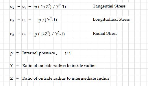
Step 2: Find out the Principal stresses for the required portion by using ASME sections along with Body ID, OD & Thickness as inputs .

1111111111111111_ffhqx2.jpg

(Note: You can find out the Z & Y formula in ASME Sec VIII Div 2 Appendix 4 in 2004 edition. For Z&Y, inputs will take from Body ID & OD, Thickness from the drawing)

Step 3: The above attached fig formula is a reference and you have to find out these three stresses for both design and test pressures.
Step 4: Calculate the Stress differences from the above principle stresses to find the maximum stress intensity (formula reference ASME Sec VIII Div 2 Appendix 4 in 2004 edition).
Step 5: Find out the FOS by calculated stress intensity for both design and Test pressures; i.e.) FOS= Sm / Stress intensity for design pressure & FOS= St / stress intensity for test pressure.

This is just an idea. hope it will help to take ur calculation further better...
Thanks... Feel free to contact if you have any further required...

Dinu...

There are no secrets to success. It is the result of preparation, hard work, and learning from failure.
 
Thank you very much Guys it was really useful
 
Hi Dinu,

Thanks.
How about this....
I tried the below as per API 6X Combined Stress. Which says stress intensity,
Si = S1-S2 (S1>S2>S3)

Therefore I calculated the three principal stresses as per Roarks formula as below,

43953566-BDBD-4199-905C-6929BD9F04EE_g8b5yj.jpg


And found the difference between maximum and the next available minimum and then the
FoS = Allowable / stress intensity

This I did for both working pressure and test pressure condition.Hope the above method is right? And this is also acceptable as per API 6X?
 
Hi HansonBoye,

Yup It is accepted by API 6X as well as API 6A.
also noted that the allowable stress intensities for FOS, have to follow as per 5.1.2 in API 6X for API 6A product.

Thanks... all the best!!!

Dinu...

There are no secrets to success. It is the result of preparation, hard work, and learning from failure.
 
Thank you very much

I have one last question ... its regarding shear pin calculation for stem.
It might be simple but i need some lead from somebody who has valve design experience.

How to calculate the shear pin failure ... to justify the shear pin fails before stem during torsion.

below is a picture for your reference.

Untitled_ednnyv.jpg


Where,
D is the stem diameter (say 1.24 in)
D1 is the stem adapter diameter (2.3 in)
d is the shear pin diameter (.44 in)
shear pin material is A36 (36K yield or 58K Ultimate tensile strength)
stem material is 410 ss (75k)

please, can you advise how to do calculate the shear pin failure ...
Thanks
 
Hi Dinu,

I have one more clarification.
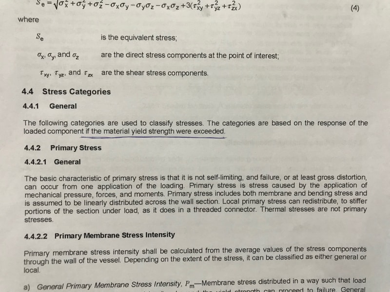
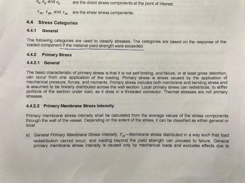
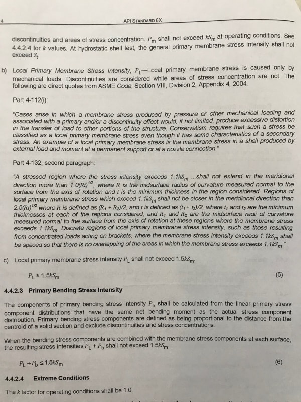
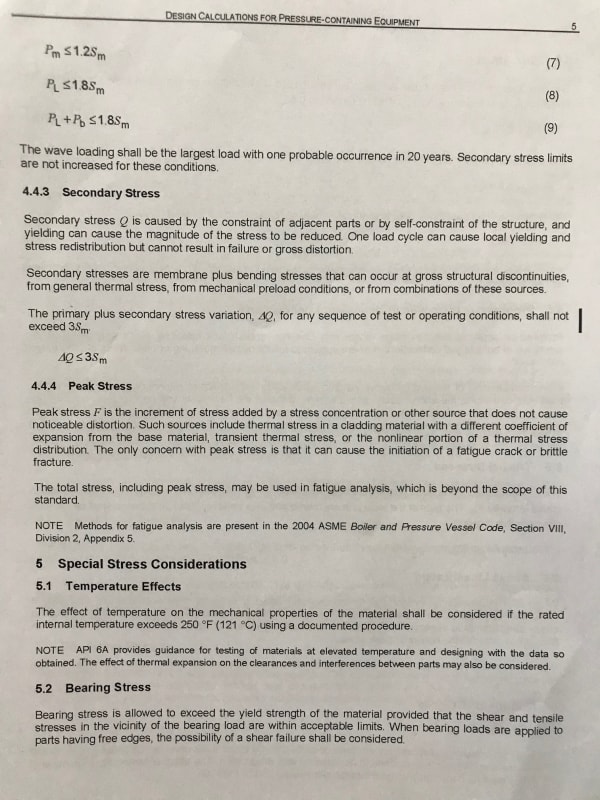
As per the API 6X second edition. Section 4.4 Stress Categories, is it mandatory to calculate the primary + bending stress? and the secondary, peak stresses?
The reason I ask is the section 4.4.1 says that the stress "The categories are based on the response of the loaded component if the material yield strength were exceeded." Below are the references from API 6X Second Edition.

image0_xdjbnl.jpg

image1_it4fsk.jpg

image2_exyrsy.jpg

image3_zgweji.jpg


Please let me know if you using these in your calculations?
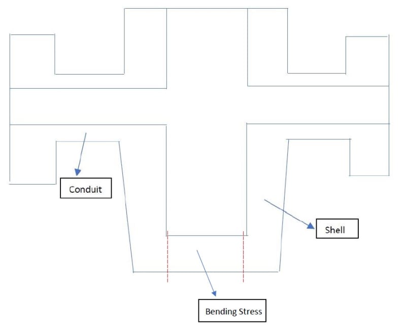
For example: for the gate valve body shown below, for wall thickness analysis at Shell and Conduit, i only calculate the von mises equivalent stress as per distortion energy method and stress intensities as per roarks formula that we discussed sometime earlier. In this case i would calculate the primary + bending stress for the shell as there would a bending stres at the shell bottom as shown in the pic below? i dont see there is any bending load acting on the body conduit.. or in reality we dono where the gate valve will be used and what load will be on the conduit flange (API 6A spec). Kindly let me know if im correct, if not please clarify.
Pic111_gg4pad.jpg


Sorry for the long message... hope you can clarify .. thanks

Regards,
Hanson
 
Hanson,

I had a quick review and i have found, attached photos is not the latest standard edition of API 6X.
it may be a draft copy / previous edition which cannot be used. also the underlined sentence is given in the annex as an informative in the new edition which is clearly stated as optional (No need to follow / need to follow)...

Please try to read the new latest edition of API SPEC 6X...

For reference: Index page can download and compare with your current 6X standard...
I will have look on your post once again and give my suggestion as much as i can...

Thanks and sorry for taking further more time to think about this...

Dinu...

There are no secrets to success. It is the result of preparation, hard work, and learning from failure.
 
Hi Dinu,

Yes you are right. I was looking into the API 6X first edition instead of the Second.

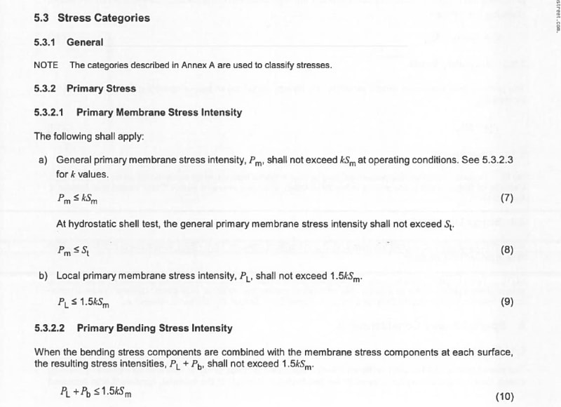
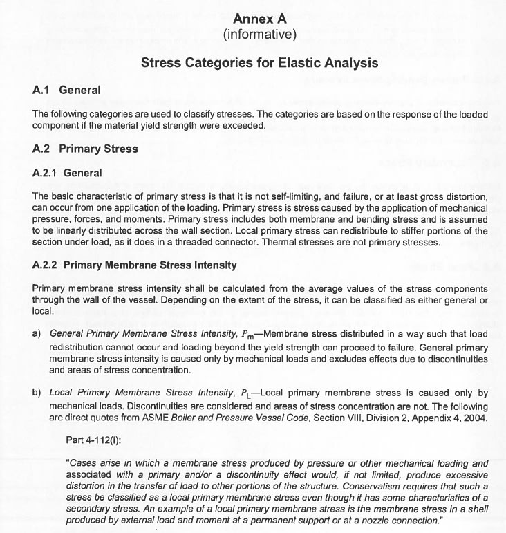
But still, in the second edition they called it as informative - an additional reference to the main content Section 5.3 Stress categories.

1_dr73df.jpg


2_usdzzn.jpg


But in the main section, they didn't say its informative ie., in section 5.3 they have given an overview of the stress categories with reference to Annex A

In general, in API terms anything informative is not mandatory and no need to comply. But as the general note in Annex A says "The following categories are used to classify stresses. The categories are based on the response of the loaded component if the material yield strength were exceeded" we can comfortably neglect these i guess.

Thanks!
 
But thanks for your replies..
I have three more questions to discuss...
1) For the gate valves ..parallel slab gate..to find the gate deflections what method are u using? Although there wouldn't be much deflection on the gate, I'm using the deflection formula from Machinery Handbook (see below)to justify this as a supportive calc. Where W is the force due to upstream pressure acting on the gate at the gate and seat interface.
Do you think this is required?

3_ehrlx7.jpg


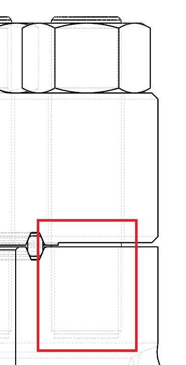
2) For the body bonnet bolt stress, i go only as per the ASME VIII Div 2 method of calculating the bolt stress at operating conditions and gasket seating condition. My question is doing so, we aren't calculating the capacity of the body itself to withstand the bolting stress produced. How to justify if the body can withstand all the stress due to bolting force. I mean in the body section area shown in the below image.

Untitled_yt6i0i.jpg


3) The ring gasket that we use for the body and bonnet sealing is a non-api gasket. Is there a method to design this non-standard gasket? as i hardly see any references to identify the geometry size for the gasket and the tolerances. I took the API 6A BX Ring gasket and groove size and altered geometry to match within the valve body and bonnet thickness. I know it will still work, but i need to justify this with a classical method calculation. Any suggestions or directions would be much appreciated.
 
Hi Dinu,

Thanks for your replies.
Do you have time to discuss on my thread above. Appreciate your help.

Thanks
Hanson
 
Hi Hanson,

if we want to discuss i need to study your thread completely and think related to that in terms of design. since i am not into gate valve design... related to general design factors, we can discuss... unfortunately i have got struck into API 6A auditing work which is scheduled in coming forth month... so hardly i could not get time for the other works...

Meanwhile some quick suggestions about your thread...

Thread 1 - Annex 1 will be an informative and it is a reference guide for used to identifying the stress categories which is really gonna help you for the section 5.3.

Thread 2:

1.Really i am not into gate valve design... i am into chokes and control valve.. if any thing related to chokes i can be detailed...

2.For Body Bonnet Bolting, ASME Sec VIII Div 2 method is OK... but you have to consider the total design pressure for the calculation. if you follow ASME section VIII Div 1, there will be a formula which includes stress constants and rated working pressure. (i will send the detailed steps once i get time... give your email id or please send an email to haidinu@hotmail.com)

3. if the gasket is for flanges, you have to follow the API 6A. if the gasket is for body bonnet sealing, you can design your own gasket also. but you have to ensure it should work. there is no method for non standard gasket design. but there is a method for designing the gaskets which is standard. it includes tolerances and clearances. you can take this as a reference and can use the same method for your customized gasket design.. some of the supplier having the non standard design for the metal gaskets. i can suggest, you can create one design guideline for the body bonnet sealing by metal gaskets by help of flexitallic or other gasket suppliers and verify by experimentally and use the same document for the further design process. Flexitallic have a gasket design handbook which is available in the google / their sites.

Thanks and Sorry for the delay... once i completed my works, we can discuss in detail.. also you can ask our people from the forum too...

Thanks...

Dinu...

There are no secrets to success. It is the result of preparation, hard work, and learning from failure.
 
Status
Not open for further replies.

Part and Inventory Search

Sponsor