Hello,
I am creating a custom flange for a Horizontal Low Water Cut Out Switch. I am struggling to see how flanges can pass the rigidity factor calculation.
My question is how do any flanges pass this check or am I misunderstanding something?
The goal is to minimize the size and weight of this product and in doing so, eliminates the possibility of using B16.5 Flanges.
The maximum Operating Conditions for boiler service = 1000psi at 550F.
Design conditions = 1250psi at 570F.
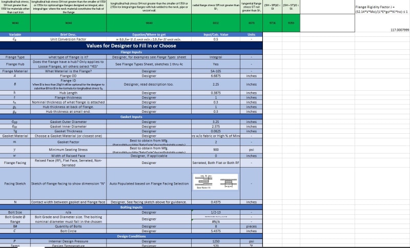
I created an excel spreadsheet that calculates everything for ASME BPVC VIII App.2 and just went through and manually calculated to make sure it was functioning properly. The custom flange meets all of the design checks EXCEPT the flange rigidity factor calculation. I attached a screen shot of the inputs below.
The flange is designed in a way to be similar to a weld neck flange (integral flange). The chamber is a 3" Sch.80 SA-106 pipe, the Flange is made out of SA-105 and it is being butt-welded to the pipe.
The 0.300" is making the rigidity factor calculation solve very high since it is in the denominator and being squared. I even input a 1500# 3" Weld Neck Flange dimensions and it was still >1...somewhere around 38 or so if I remember correctly.
Equation = (52.14*V*Mo)/(L*E*go²*Kl*ho)
V = .1583
Mo = 22871
L = 2.6854
E = 27090
go = 0.300
KI = .3
ho = .8216
I am creating a custom flange for a Horizontal Low Water Cut Out Switch. I am struggling to see how flanges can pass the rigidity factor calculation.
My question is how do any flanges pass this check or am I misunderstanding something?
The goal is to minimize the size and weight of this product and in doing so, eliminates the possibility of using B16.5 Flanges.
The maximum Operating Conditions for boiler service = 1000psi at 550F.
Design conditions = 1250psi at 570F.
I created an excel spreadsheet that calculates everything for ASME BPVC VIII App.2 and just went through and manually calculated to make sure it was functioning properly. The custom flange meets all of the design checks EXCEPT the flange rigidity factor calculation. I attached a screen shot of the inputs below.
The flange is designed in a way to be similar to a weld neck flange (integral flange). The chamber is a 3" Sch.80 SA-106 pipe, the Flange is made out of SA-105 and it is being butt-welded to the pipe.
The 0.300" is making the rigidity factor calculation solve very high since it is in the denominator and being squared. I even input a 1500# 3" Weld Neck Flange dimensions and it was still >1...somewhere around 38 or so if I remember correctly.
Equation = (52.14*V*Mo)/(L*E*go²*Kl*ho)
V = .1583
Mo = 22871
L = 2.6854
E = 27090
go = 0.300
KI = .3
ho = .8216
")