Continue to Site

Eng-Tips is the largest engineering community on the Internet

Intelligent Work Forums for Engineering Professionals

  • Congratulations KootK on being selected by the Eng-Tips community for having the most helpful posts in the forums last week. Way to Go!

Appllying bolt pretension load in Abaqus Explicit Solver

Status
Not open for further replies.

Tinni1

Civil/Environmental
Sep 27, 2021
157
Hello,

Using a dynamic explicit solver in Abaqus, I am performing a post-buckling quasi-static analysis of thin-walled (2 mm thick) cold-formed steel C sections connected to a U section at both ends.

As per my model geometry, the U-section is connected to hot rolled steel loading plates (12 mm thick) at both ends with M8 bolts, 4 numbers on each side.

I am applying the bold pretension load using two different files.

In the first file I performed a static analysis using bolt load command.

In the second file I imorted the deformed geometry of the first analysis file as imperfections.

My queries are:

1. Is the method that I employed correct?
2. Could you please direct me to any references of chapters of ABAQUS manual about this?

Many thanks in advance!
 
Replies continue below

Recommended for you

Why are you bothering with bolt pretension? Or even bothering with modelling the fasteners at all?
Thin gage structure in a post-buckling state should not be critical in the bolted joint areas.
 
Yes, I agree.

I modeled it for only one benchmark analysis, for checking.

The analysis provides correct results when bolt pretension is not modeled.

With the pretension, I am getting an artificial increase in the column capacity and also an incorrect failure mechanism that does not match my test results.

That's why I want to check if the pretension analysis method , I am following correct or incorrect.
 
I would start by closely examining the displacement results from both models.
 
What elements are you using to model the bolts ? What happens to them after import ?
 
Hi, thanks for your response.

I am using solid elements of 1mm x1mmx 1 mm mesh size.

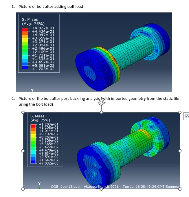
I am attaching two pictures:
1. The picture of the bolt after adding the bolt load (7 N).
2. The picture of the bolt after the post-buckling analysis where imported geometry from the bolt load file was incorporated as imperfections.

There is no much visible difference between the two. However, the post-buckling analysis gave me a 16% higher column capacity than testing.
Although the slope of the load-axial displacement curve is the same with and witout bolt load.


bolt_load_zsxd1g.jpg
 
Instead of showing us this ridiculous bolt mesh, please show the column buckling mode and displacements for the two models.

 
My answer was against the previous question about bolt meshing only
 
If done correctly, the approach with pre-loading bolts in Abaqus/Standard and importing the model to Abaqus/Explicit is reasonable. But it makes sense mostly for models focusing on joints themselves. If it's just a part of a large structure, it might be better to model the bolts in a more simplified way using 1D elements. Connectors are really good for that and you will be able to apply pre-tension more directly.
 
That's great! thanks for your response. I will try using connectors
 
Status
Not open for further replies.

Part and Inventory Search

Sponsor