Eng-Tips is the largest engineering community on the Internet

Intelligent Work Forums for Engineering Professionals

Appropriate Skeletonization of Chilled Water Network Hydraulic Model 1

Status
Not open for further replies.

IanVG

Mechanical
Jan 21, 2022
73
0
0
US
As the title suggests, I have been tasked with modeling my campus' (University of Georgia) hydraulic chilled water networks. I am fairly familiar with using the appropriate equations and methods for modeling pipes in series and in parallel with series and parallel pumps for smaller loops (think water source heat pump loop at two buildings), but when diving into the models that past consultants have provided I start scratching my head. My goals are:

[ol 1]
[li]Modeling flow and pressure conditions along the primary side of the system (i.e. up to building taps). This is to verify pipe sizes and unexpected pressure drops based on model vs. real-world measurements.[/li]
[ol A]
[li]Adding new secondary systems (i.e. buildings) to primary system and understanding effect.[/li]
[li]Sizing new pumps and devices for primary system side.[/li]
[/ol]
[li]Diagnosing in-building (secondary) system failures.[/li]
[ol A]
[li]Low-flow conditions AHU’st.[/li]
[li]Reverse-flow conditions at AHU’s.[/li]
[li]Low (insufficient) D.P. at AHUs’ control valves.[/li]
[/ol]
[li]Modeling varying loads throughout the system.[/li]
[ol A]
[li]Starting with binary 0% or 100% (on/off) states for each building moving to fully adjustable 0-100% loads (moving from 0-100% for the building to 0-100% for each FCV that is ‘significant’).[/li]
[/ol]
[/ol]

With that being said, as long as the skeletonized (simplified) model I create meets those goals in order, then the model is providing the necessary utility. I’ve been looking into methodologies for the skeletonization of campus district energy models to help me determine what level of detail is needed at each step, with relatively little luck for a similar kind of system (primary-secondary) we have at our campus.

Some ideas I have are to model each building as demand flows, then to move slowly towards modeling the entire building out (simplifying parallel and series resistances where there are no control valves or where adjustable control valves are deemed to be opened 100% for simplicity’s sake). I guess my question is with those goals and system in mind, what is the typical level of simplification allowable moving from building-as-demand-flows to fully fleshed out buildings?

Answering this question will help me to:
1. Talk and guide outside engineering firms towards appropriate modeling of our campus.
2. Refine existing models.
3. Create new models and any necessary testing methods for calibration of the model.

Namely, the assumption I am questioning is whether an entire building (building w/o pumps) connected to the loop can be modeled as a control valve set to a GPM and constant DP device. I am using Pipe-FLO to model our networks.

I am open to any and all thoughts on this matter.
 
Replies continue below

Recommended for you

Since its a chilled water system, I suggest approaching the system design from a loop perspective as the system is not a linear supply to a consumer. The system is a loop, as are each unit smaller loops within the larger.

Start with the main line loop to the farthest point, get that running, then add details beginning with the largest loads, progressing to the smallest.

Rather than modeling as demand flows, model each building loop as a simple hydraulic element, basically a "one short pipe of some diameter D that will give you the expected or estimated pressure drop of that load when fully completed to your ultimate level of detail.

Then start replacing that "one pipe loop" with the actual equipment and individual pressure drops as you add detail to each load unit on the main loop. Initially model only block valves and check valves to /from each unit. Add any needed control valves later, only as you determine that there is a need for them.

If you start with demands and flows with set points, or control valves controlling those flows, you might never discover the difference between choosing the correct pipe diameters as you let the control valves complicate the pipe diameter selection with their added pressure drops. You will waste a lot of time with control valve sizing vs %Open and positions and dP, rather than just concentrating on getting the pipe sized correctly. That's where you need to start. You might also never be able to get all the valves working together, rather then fighting each other. You should be able to model the basic system using only pipe to distribute flow. Control Valves can then be sized later only to finely control loads from low to high ranges required by each unit and you won't wind up with a bunch of unnecessary valves simply fighting each other.

Don't over model everything at once. Go step by step when adding detail. Only add detail sufficient and as necessary to proceed to the next step.

--Einstein gave the same test to students every year. When asked why he would do something like that, "Because the answers had changed."
 
Thank you for the advice 1503-44! Just to clarify, my intent is to model our existing chilled water loops. I.e. I know that there are many flow control valves operating based on the leaving air temperatures' of many different AHU cooling coils. So are not the control valves all necessary? Knowing what the best approximation of (for example) three parallel branches to three different coils with three different control valves is something I am still scratching my head over. Previous consultants modeled (for example) the three parallel branches with one constant pressure drop device and a flow control valve. I'd like to improve upon, this but we haven't even calibrated the model we received yet, so I don't know if the assumption they made was good. I haven't found any other examples (at least on the internet) of other universities that have experience with developing a hydraulic flow model, so I don't know if the constant pressure device in combination with a flow control valve is a good approximation of parallel curve DP devices w/ flow control valves.

In addition just to clarify, some of the buildings feed directly off the loop, while other have building pumps that maintain a constant DP at the farthest coil in the respective building. I suspect I need to add all building pumps to get a good understanding of the system.
 
It does sound like a complicated system.
1. First the hydraulics must make sense.
Controlling Air temperatures is an "operational flexibility concern."
That usually requires only relatively minor adjustments to flow rates, probably all similar, as cooling amongst all units in one particular loop will be very nearly the same. If they are not similar, they should have been put in a different loop. They were grouped like that for a reason...presumably.
2. Pressure and flow controls will typically fight each other, so since flow variations should be minor, I would rather get the loop pressures right first, establishing sufficient aggregate flow to each loop. Then let air temp/flow control valves make small adjustments to the aggregate flows, setting flows into each branch. Get the pumps working well with the pressure controls valves setting aggregate flow supply to the loops. Initially set all flow control valves inactive and at full open. The flow control valves can be activated later to see how branch pressures are affected.
Any loop pressure variations that result from them should be within the range of pressures going to the loops that the pipes, pumps and pressure control valves can supply.

I think that is probably what the previous consultants did. No other logic would make much sense to me.


--Einstein gave the same test to students every year. When asked why he would do something like that, "Because the answers had changed."
 
It may help to think of chiller system design a bit differently from water distribution systems.
In fact it may be such that (most) of the "flow control" valves are actually Temperature control valves.

All control valves open/close to a particular position based on some type of feedback signal. What signal they get determines if they are flow, pressure, temperature, level, speed, mixture composition, or other type of control valve. What flow and pressure you get at various parts of the system corresponds to some %Open of the valve. The hydraulic response in terms of variables you measure flow, pressure, temperature, or other, for each valve is felt throughout the system. Generally the farther away from any given valve, the response measure becomes less and less. Typically the response is some form of a pressure (or head) verses flow chart, as is a typical "system curve", but if you measure temperature, it will be more convenient to see a temperature vs flow chart. A hydraulic system is sort of an analog computer. If you give it temperature input, it automatically converts that to a hydraulic equivalent and proportions flow accordingly, for which you can then separate the variables into the hydraulic response, an output of flows and pressures at all points throughout the network.

--Einstein gave the same test to students every year. When asked why he would do something like that, "Because the answers had changed."
 
I think you might be searching for the holy grail here....

To move this forward, I think we really need to see some example sketches of your system, what is happening and then how you think it is best to model it.

SO e.g. "Knowing what the best approximation of (for example) three parallel branches to three different coils with three different control valves is something I am still scratching my head over. "

Can you sketch this out so that we can see what you are looking at?

Remember - More details = better answers
Also: If you get a response it's polite to respond to it.
 
LittleInch - yes, the flow control valves in the buildings are all set to open or close based on the leaving air temperature of the AHU coils. I noticed in the software I am using (Pipe-Flo), if I replaced the FCV (does not really exist, just a stand in to 'force' a certain flow to a building) and its adjacent fixed DP device with simplified building loop (pump and one control valve with a fixed DP device to force a differential pressure, no difference is made on the loop. I.e. no difference on the building supply DP and the building return DP.

Loop___Building_Setpoints_n92fdn.png
Secondary_Variable_System_qfmzcc.png


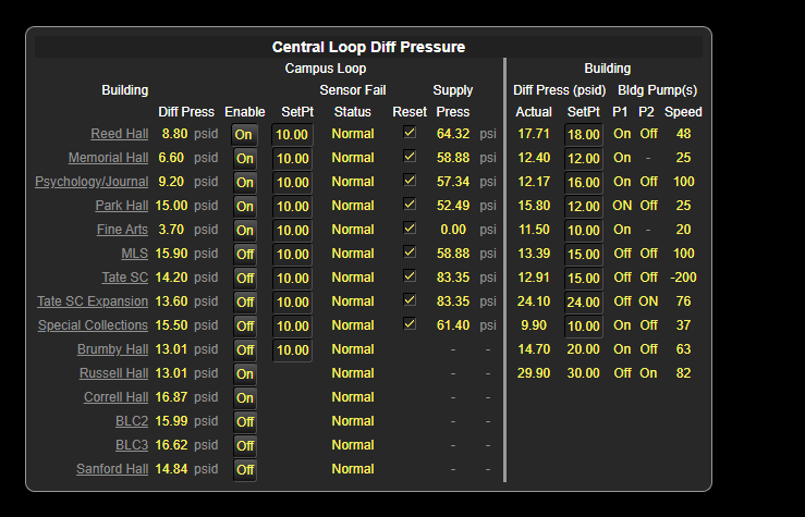
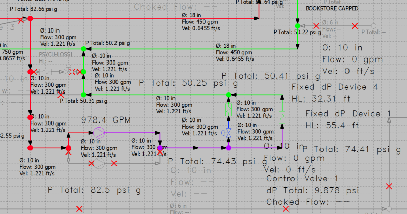
I am also uploading the a picture of how our BAS controls the district energy plants' pumps based on the building DP setpoints and also the building's DP setpoints that are achieved by in-building pumps. Let me know if any of this helps. I am also attaching a PDF of two things: one is a schematic of one of our campus chilled water loops and another is how that loop was modeled in Pipe-Flo. So you can see what was simplified.


Okay, for some reason I was getting a real mental block on this one, but I had a meeting with another engineer in my office and we figured it out. I'll try to sum it up below: if anyone has any questions, I can try to follow up.

I misunderstood the fundamental nature of the network I was dealing with. Based on the configuration of the building connections to the network, there is no possibility of simplifying the network to fixed DP drops. The network is a variable primary-variable tertiary type loop. This layout is similar to a primary-secondary-tertiary setup, sans the secondary portion of the loop. If you look up a basic configuration for a primary-secondary-tertiary water loop, you'll notice that the secondary loop contains some sort of pumping system to maintain flow and pressure in the distribution loop. The primary (i.e. the side of the loop responsible for distributing out chilled water) contains a pumping system that is only responsible for pumping water through the chillers' evaporators out onto the network. For some reason (likely energy based reasons) we built out a system that is dependent on the primary side (i.e. the pumps at the chiller plants) to supply water throughout the loop. However, because there is no hydraulic separation between the distribution loop and the tertiary loops (i.e. the building loops) the building pumps are nearly always running to maintain a building D.P. even when there is sufficient distribution loop pressure to do so. That latter modifying clause is important, because basically what can happen is that pumps can 'overpressurize' the return side of the loop thereby causing reverse flow in certain portions of the loop. Reverse flow has all sorts of bad consequences, including but not limited to unwinding some part of the pumps (pump impellers are meant to rotate in one direction), and uncertain heat transfer due to unintended flows in buildings. Check valves will limit which portions of the system can have reverse conditions.

Many of the buildings I have been looking at, have not been designed with any sort of bypass around the building pumps delivering chilled water from the distribution loop to the coils in the building. That means the lowest positive DP the pump can provide (if the pump has a VFD/VSD) is whatever the lowest frequency of the VFD is. This may be somewhere around 5-20% of the maximum frequency (e.g. 60 Hz) that the VFD can do. It is possible that under a no power condition, the water could flow through the pump and the pump would act as a pressure reducing device. However, unlike the pump curve which defines the flow characteristics of a pump under powered conditions, there are no graphs or reasonable expectation of how much the pump would reduce pressure at various flows. Therefore any modeling that you build of a system, can be basically thrown out the window.

The inability of a building to reduce pressure from the building loop, means that even if there is sufficient loop differential pressure to satisfy the needs of the building, the building in incapable of reducing the incoming pressure and the best it can do is only slightly increase pressure or maintain (no change) the incoming pressure.

In addition (this is the part I don't quite understand), there is a possibility on the MHRL (most hydraulically remote loop) that the building pumps are now in a series configuration with the primary distribution pumps. Depending on whether the flow at the building loop is higher or lower than expected, the MHRL building loop pumps can pump more water than expected, thereby causing the building pump to "run off the curve." This has negative consequences of causing the motor to fail earlier (overheating of the winding, I would think?, I'm not 100% clear on this).

Regardless, the consequences of designing a primary-tertiary system has been made clear to our campus as we have both reversed flow conditions and frequently failed pumps/pump motors that are connected to the chilled water loops. For the past nearly 20 years, we have commissioned engineering consultants to provide us with reports/studies/models to inform campus future expansion and modification of the chilled water districts. All of the models assumed that the building pumps have no effect on the chilled loop D.P. and flows. I believe this has led us down a path where we now have to implement modifications to how the buildings are connected to the loop. This perhaps means moving from a direct connection (as we mostly have now) to indirect connections. This could also mean that we should implement the "secondary" portion of the chilled water loop. Although this would require allocating space, funds and time to the secondary portion of the system. At minimum, in order to create a modeling twin of the physical network, I will have to collect and organize data on all building pumps associated with each building loop (i.e. replicate the pump curve at a certain impeller size for certain model pump) and input this data into the piping network model. I will also need to do the same with all the control valves for each building loop.

So back to the original question I was trying to pose - what is the appropriate skeletonization of chilled water network model? As you can see, this depends on the variant of the chilled water network model type that you have, of which there at least a handful. In my specific case, with a primary-tertiary type chilled water network with mostly only direct connections of the building loop to the chilled water network (an atypical variant of the primary-secondary-tertiary network), the simplification/skeletonization of the system is limited to sections of pipeline in series (i.e. fixed geometry devices that reduce pressure).

Because of the nature of possible overflow and/or reverse flow in the system, you cannot simplify (I think) any control valves that are in parallel in the building. Under indirect connection building connection conditions (imagine a bypass around the building pumps), you still cannot simplify the AHU coil control valves into one fixed CV device, as the excessive D.P. in the building could cause the building control valves to partially close to maintain a fixed leaving air temperature discharge off the AHU coils. However, if there is a control valve device at the building connection and an indirect connection, then (assuming that the conditions of the network don't exceed the operating conditions of the building control valve) it would be possible to simplify the AHU coil control valves into one device (meaning you find overall DP at a certain flow for the entire building and model it as one fixed CV device).

 
Any two or more parallel flow elements can be simplified to one element with a fixed pressure drop, at least until transient pressures become excessive.
 
Status
Not open for further replies.
Back
Top