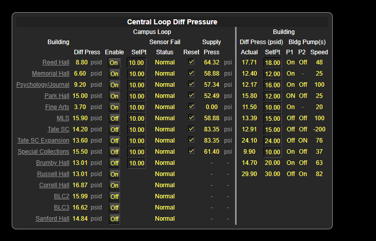
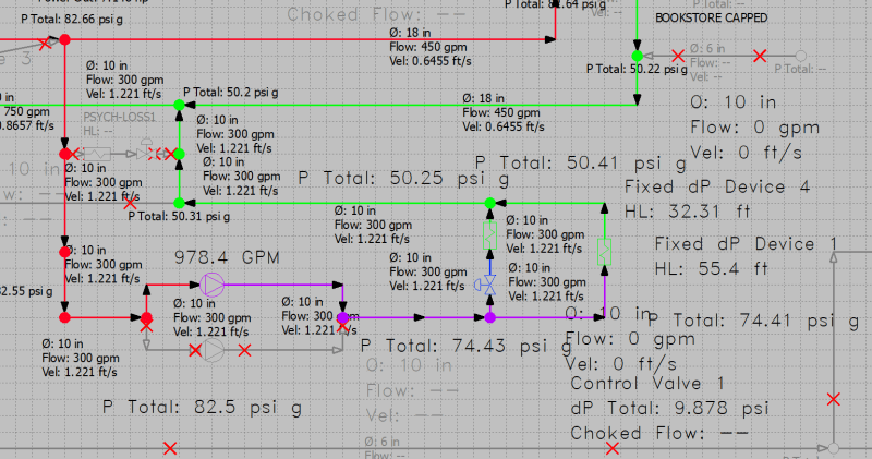
As the title suggests, I have been tasked with modeling my campus' (University of Georgia) hydraulic chilled water networks. I am fairly familiar with using the appropriate equations and methods for modeling pipes in series and in parallel with series and parallel pumps for smaller loops (think water source heat pump loop at two buildings), but when diving into the models that past consultants have provided I start scratching my head. My goals are:
[ol 1]
[li]Modeling flow and pressure conditions along the primary side of the system (i.e. up to building taps). This is to verify pipe sizes and unexpected pressure drops based on model vs. real-world measurements.[/li]
[ol A]
[li]Adding new secondary systems (i.e. buildings) to primary system and understanding effect.[/li]
[li]Sizing new pumps and devices for primary system side.[/li]
[/ol]
[li]Diagnosing in-building (secondary) system failures.[/li]
[ol A]
[li]Low-flow conditions AHU’st.[/li]
[li]Reverse-flow conditions at AHU’s.[/li]
[li]Low (insufficient) D.P. at AHUs’ control valves.[/li]
[/ol]
[li]Modeling varying loads throughout the system.[/li]
[ol A]
[li]Starting with binary 0% or 100% (on/off) states for each building moving to fully adjustable 0-100% loads (moving from 0-100% for the building to 0-100% for each FCV that is ‘significant’).[/li]
[/ol]
[/ol]
With that being said, as long as the skeletonized (simplified) model I create meets those goals in order, then the model is providing the necessary utility. I’ve been looking into methodologies for the skeletonization of campus district energy models to help me determine what level of detail is needed at each step, with relatively little luck for a similar kind of system (primary-secondary) we have at our campus.
Some ideas I have are to model each building as demand flows, then to move slowly towards modeling the entire building out (simplifying parallel and series resistances where there are no control valves or where adjustable control valves are deemed to be opened 100% for simplicity’s sake). I guess my question is with those goals and system in mind, what is the typical level of simplification allowable moving from building-as-demand-flows to fully fleshed out buildings?
Answering this question will help me to:
1. Talk and guide outside engineering firms towards appropriate modeling of our campus.
2. Refine existing models.
3. Create new models and any necessary testing methods for calibration of the model.
Namely, the assumption I am questioning is whether an entire building (building w/o pumps) connected to the loop can be modeled as a control valve set to a GPM and constant DP device. I am using Pipe-FLO to model our networks.
I am open to any and all thoughts on this matter.


