Continue to Site

Eng-Tips is the largest engineering community on the Internet

Intelligent Work Forums for Engineering Professionals

  • Congratulations KootK on being selected by the Eng-Tips community for having the most helpful posts in the forums last week. Way to Go!

Approx. 300 sq ft, 19 ft suspended architectural ceiling 2

Status
Not open for further replies.

CaPE90

Structural
Jul 31, 2024
7
Existing commercial one story building with 18" deep TJI joists

Tenant is proposing a suspended soffit/architectural ceiling 7 psf max weight as of now, 300 sq total across two areas. The ceiling is 8 ft above finish floor, and the highest point of the roof is up to 27 ft at the ridge. So a 19 ft vertical suspension at the high point and 11.5 at the low point.

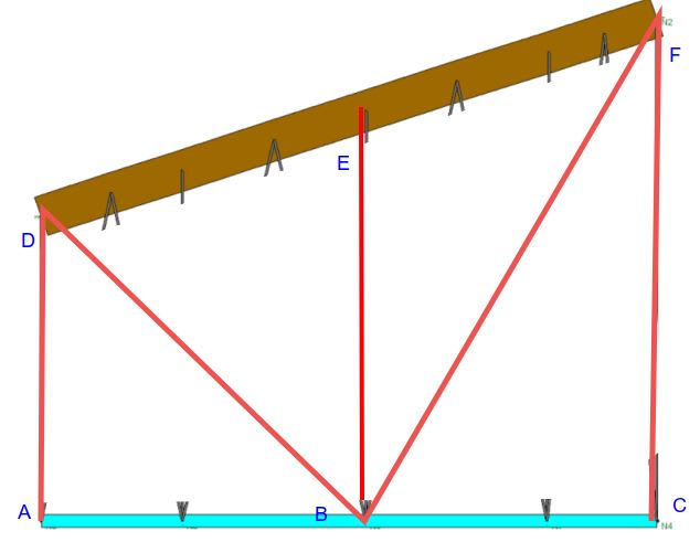
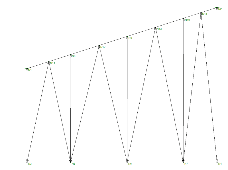
In the past I have done this with tension ties and all thread rods with enough diagonals to limit compression in the rods, but at much shorter suspension heights. Below is a rough schematic of this situation. Appreciate thoughts, guidance, etc. Do kl/r =200 and buckling apply to the rods in this orientation? It is a bit outside of my wheelhouse and I do have a RISA model but can use some help there.
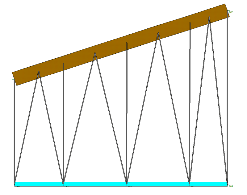
rendered_wfuxpf.png
section_bmbp1p.png
 
Replies continue below

Recommended for you

That’s a deep plenum!
I would consider kL/r=200 as a limit.
Are you able to slip tube over the threaded rod hangers to give it compression support?
 
Why are you restricting your tension diagonals to such a tight angle. If they are just rods then you can pass them over the verticals to get a much flatter angle something close to 45 degrees.
 
I could flatten the angles a bit but that would lengthen them as well.

Using kL/r as a limit, starting with 3/4" diameter threaded rods (r=0.1875), I am getting a maximum length of 37.5"
200 = (1.0)(L)/(0.1875)

To get my longest member of 18.5 ft to work, I would need a threaded rod diameter of 4.44" to work...

Something seems off or maybe I am just way off in using threaded rods. How would you detail tube steel over the threaded rod hangers? I was planning on attaching these rods to Simpson HTT/HDU type brackets at the wood framing and cold formed soffit.

Is my idea that I have enough diagonals for them to resist the movement in tension only incorrect?
 
Why are you applying kL/r to threaded rods under tension?

Or am I missing something here? This seems a tension only setup.
 
What is the span? Have you considered suspending a member at ceiling level and eliminating most of the rods?
OP said:
Is my idea that I have enough diagonals for them to resist the movement in tension only incorrect?
It is incorrect if you are expecting truss action, but it should work provided the top joist can sustain the additional ceiling load. In fact, you could eliminate all of the diagonals and use only the verticals. And kl/r for tension members can be 300, not 200.
 
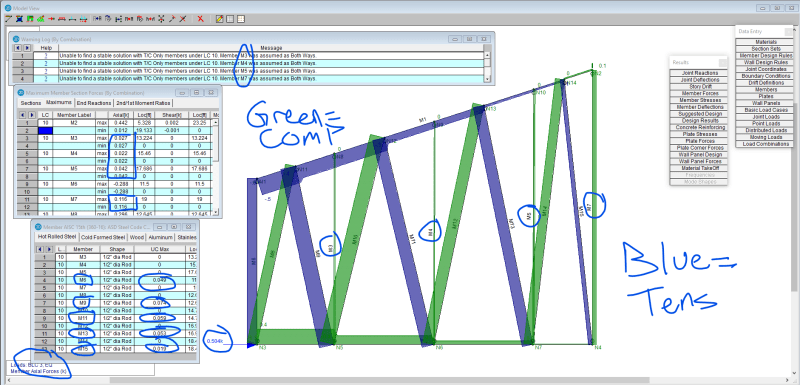
Below is the RISA model under nonstructural seismic anchorage loading in SDC E. The soffit consists of cold formed box beams to answer BAretired. All of the vertical and diagonals are set as Tension Only, but it seems there is compression in the circled members. For design results, I am only getting stresses in the tensile members.
Screenshot_2024-08-03_103146_muqcxs.png


Risa doesn't appear to check kl/r for tension only members. When they were set to Both Ways, it gave the kl/r failures. Does kl/r apply to tension rods?
 
You are confused. You can't dictate that all web members are tension members. If you are considering the structure as a truss with uniform load, the green members are in tension and the blue members are in compression. The vertical members should be removed as they are redundant.

This is the wrong approach, imo. Better to provide a structure at ceiling level and get rid of a forest of rods.

 
The ceiling is suspended from the roof....there is no structure at ceiling height to tie into. It is a 300 sq ft suspended ceiling at 8 ft above ground level, hanging from the roof structure up to 18 ft above the 8 ft.

I am not at all concerned about the gravity load. I am needing to resist a horizontal nonstructural seismic anchorage load at the soffit level. Without the vertical anchors, there is nothing supporting the gravity weight. Without the diagonals, there is no lateral bracing.
 
Are you looking at a load combination that includes ceiling dead load, or just a single load case of lateral seismic only?

The former might give enough gravity load in those hangers so the model converges. The latter would be unstable with all "tension only" members.

In RISA you can also assign "euler buckling" behavior to the members so they can take a very small but not zero amount of compression allowing the model to converge.
 
Klitor said:
Only green verticals could be in compression and would therefore need to satisfy kL/r<200
Good solution! Actually every bar could be in compression, depending on the direction of lateral load, but the tension diagonal can be assumed to act without a contribution from the compression diagonal.
 
I'm still confused on:
-why you are so eager to include compression members
-why you are so eager to have your lateral bracing inefficient and impractical angles
-and why if you do want to inlcude compression member you don't remove half or more of you lateral diagonals


PMR06 said:
Are you looking at a load combination that includes ceiling dead load, or just a single load case of lateral seismic only?

The former might give enough gravity load in those hangers so the model converges. The latter would be unstable with all "tension only" members.
This would seem to be the case. It does seem to be a case of somebody who isn't thinking outside what the computer model says.

CaPE90 said:
All of the vertical and diagonals are set as Tension Only, but it seems there is compression in the circled members.
So where is your dead load?
 
To resolve the forces there may need to be a compression member, depending on DL and seismic load. Personally I would make it the vertical due to the shortest length. Rods are not efficient for compression so I would use an angle or something like that.

The diagonals should all be tension only, maybe even with cables such as the Gripple wire rope system.

 
Challenging project. Personally, I would probably approach the design of this assembly with cold-formed steel, assuming you haven't ruled that out. I suspect the connections/detailing for resolving the ceiling frame loading into the TJI rafter will provide the clearest direction for designing the ceiling support frame itself.
 
If I understand this right, you need compression members for seismic uplift forces, correct?
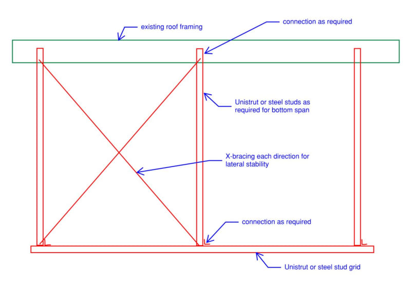
Assuming yes, I would tend to hang a steel stud or unistrut type structure frame from the structure above and have those 90 degree vertical members act as compression members (chances are if they work for compression at that length, they will be sufficient for tension in the opposite load case). I would then add cable or rod bracing at 45 degree angles each direction for lateral stability. I wouldn't even consider looking at this from a standpoint of a truss.

Capture_egwk8z.jpg
 
So is this a ACT/drop-in type ceiling or a hard ceiling (sheetrock, etc) cloud?

Either way, what's wrong with just suspending the grid (like Aesur suggests) from 12ga wire as pretty much every other suspended ceiling is supported? There are tons and tons of details and references for exactly how much bracing is required per sq. ft. of suspended ceiling for high seismic design cats. Pretty much you just hang everything from wires then provide steel stud bracing every xxx (300?) sq. ft. The steel stud bracing consists of diagonals and compression studs. No need to brace every single vertical.

Otherwise I'd agree with Aesur's suggestion.
 
Status
Not open for further replies.

Part and Inventory Search

Sponsor