Continue to Site

Eng-Tips is the largest engineering community on the Internet

Intelligent Work Forums for Engineering Professionals

  • Congratulations IDS on being selected by the Eng-Tips community for having the most helpful posts in the forums last week. Way to Go!

ARC LENGTH GAUGE 2

Status
Not open for further replies.

markaugust30

Mechanical
Sep 30, 2017
9
Hi Guys,

Need Some help. Im new in designing checking fixtures and gauges.
can somebody tell me if there is something wrong with the tolerances I put.

Capture_t48tad.jpg

Capture2_ubbvvt.jpg


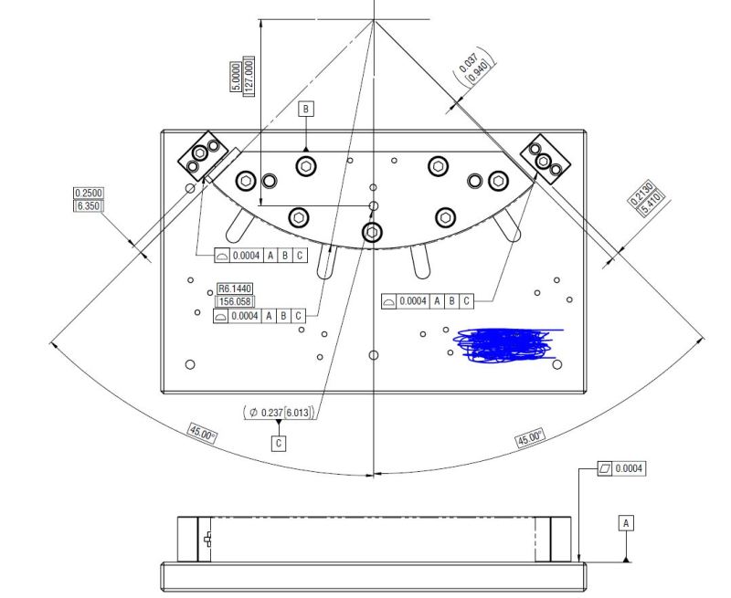
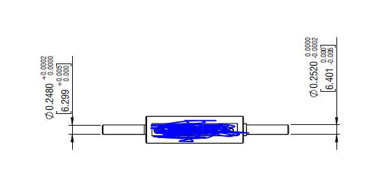
I need to check a part's arc length by using Go Nogo gauge.

the part image below and its tolerance.
Untitled_v6f5oy.png


to use the gauge is by sliding the Go Nogo gauges on both sides of the part.
see image below.
Capture3_wswmi8.png


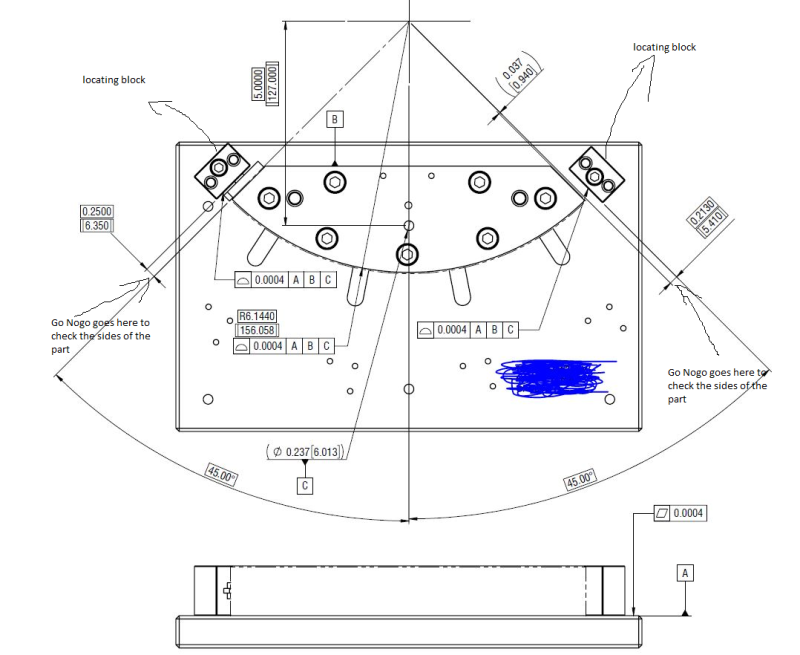
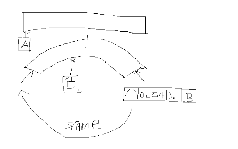
Basically My Problem is How do i decide the tolerance to put on my Gauge Fixture since we know we have machining
tolerance and assembly tolerance.
let me know if its not clear to you.

Thanks!
 
Replies continue below

Recommended for you

I am not much in to hard gauging - we use portable CMM and laser trackers. The Standard Y14.43-2003 discusses tolerancing concepts, but as I remenber it, there is no stated rule for gauging tolerances (based on some variable of other characteristic). I have read of a 10% rule that is generally applied. Basically, you "steal" ten-percent to the feature tolerance for the gauge. So the gauge will never accept a bad part and will reject parts that are right at the limit. Maybe others can offer something more definitive.

Certified Sr. GD&T Professional
 
Copy-paste different thread

Gage Tolerancing Policies

Gages must be toleranced. There are three gage tolerancing policies commonly practiced throughout the
world. These policies are known as: Optimistic Tolerancing, Tolerant Tolerancing, and Absolute Tolerancing
(also called the Pessimistic Tolerancing approach).

Optimistic Tolerancing is not an ANSI-recommended practice for gages. It assures that all parts
within specifications will be accepted by the gage. Most of the technically out-of-tolerance parts being
inspected by the gage will be rejected, but a small percentage of technically out-of-tolerance parts will be
accepted. This policy is accomplished by tolerancing the gages from their appropriate MMC or MMC
concept virtual condition boundary so that gage pins can only shrink and gage holes can only grow from
these boundaries. This method subtracts material from the gage so that gagemaker’s tolerances, wear
allowances, form tolerances and measurement uncertainties all reside outside the workpiece limits of size
and geometric control.
Tolerant Tolerancing is also not an ANSI-recommended practice for gages. It assures that most parts
within specification will be accepted by the gage. Most of the parts outside the specification will be
rejected by the gage. A small percentage of parts outside the specifications may be accepted by the gages
or a small percentage of parts that are within the specifications may be rejected by the gages. This policy
may either add or subtract material from the gage MMC boundary or MMC concept virtual condition
boundary since the tolerance is both plus and minus around these boundaries. This means that some of
the gagemaker’s tolerances, the wear allowances, the form tolerances and the measurement uncertainties
reside both within and outside of the workpiece limits of size and geometric control.

Absolute Tolerancing is recommended. This type of gage tolerancing means that gage pins are
toleranced only on the plus side of their MMC concept virtual condition boundary (only allowing them to
grow) and that gage holes are toleranced only on the minus side of their MMC concept virtual condition
boundary (only allowing them to shrink). This has the effect of rejecting all parts not within tolerance and
accepting all parts that are within tolerance except those borderline parts that fall within the range of the
gage tolerance. Part features that are produced within the range of the gage tolerance are rejected as
though they were not in compliance with their geometric tolerance, even though technically they are
within the design specification limits. This is the price we must pay if we choose to accept no parts that
have violated their tolerance.

Absolute Tolerancing is the ANSI-recommended practice of applying gage tolerances so that the gages
will reject all workpiece features that reside outside of their specifications. This is to assure complete random
interchangeability of mating parts in an assembly inspected by these gages. Gagemaker’s tolerances, wear
allowances, form tolerances and measurement uncertainties of the gage are all within the workpiece limits of
size and geometric control. These gage tolerances add material to the gage. The gages are dimensioned at the
MMC limit or MMC concept virtual condition limit of the feature being gaged, then toleranced so that gage
pins can only get larger and gage holes can only get smaller. This policy is based on the gaging premise that
all parts not within tolerance will be rejected, most parts that are within tolerance will be accepted, and a small
percentage of in-tolerance parts that are considered near the borderline between good and bad will be rejected
as though they had violated their tolerance requirements.

The ANSI-recommended amount of tolerance is 5% of the tolerance on the feature being gaged plus
an optional 5% of the tolerance allowed for wear allowance. This recommendation is only a place from
which to begin the decision as to what tolerance will be assigned to the gage. Using the Absolute
Tolerancing method, the actual amount of tolerance chosen will depend on the number of parts the gage
will accept and the number of parts one is willing to reject with the gage. It is a balance between the cost
of the gage and the cost of the rejection of good parts by the gage. The smaller the gage tolerance, the
more expensive the gage and the quicker the gage will wear beyond acceptable limits and begin to accept
bad parts. On the other hand, the larger the gage tolerance, the less expensive the gage. However, the gage
will run the risk of being produced at a size that will reject a larger number of produced parts that are within
tolerance but near the borderline.


greenimi: Your post pretty much says it all.

Certified Sr. GD&T Professional
 
greenimi

that was very informative. THanks!

By the way may i ask, can you use a profile tolerance to control the position of a surface?

you may refer to the drawing again and see the profile tolerance control. if i want to control the position and angle of
the locating block, can i use a geometric profile tolerance instead of using direct dimension with symmetric tolerance?
 
markaugust30 said:
...can you use a profile tolerance to control the position of a surface?

you may refer to the drawing again and see the profile tolerance control. if i want to control the position and angle of
the locating block, can i use a geometric profile tolerance instead of using direct dimension with symmetric tolerance?


- Can you use a profile tolerance to control the position of a surface?

- Can you use a profile tolerance to control the LOCATION of a surface? : yes, you can.

Use profile for the surface location. You can use position to locate only the features which are features of size=FOS (has opposing and parallel elements)--there are some exceptions (irregular FOS, but I will let them out for now.

1.3.32.1 Regular Feature of Size. regular feature of
size: one cylindrical or spherical surface, a circular element,
and a set of two opposed parallel elements or
opposed parallel surfaces, each of which is associated
with a directly toleranced dimension. See para. 2.2.
1.3.32.2 Irregular Feature of Size. irregular feature
of size: the two types of irregular features of size are as
follows:
(a) a directly toleranced feature or collection of features
that may contain or be contained by an actual mating
envelope that is a sphere, cylinder, or pair of parallel
planes
(b) a directly toleranced feature or collection of features
that may contain or be contained by an actual mating
envelope other than a sphere, cylinder, or pair of
parallel planes.

Your location block: its width and its length are FOS so you can use position to locate their centerplane. In that case you don't need profile.
If you choose to use profile, I would say that the width should be basic. If you choose to use position the width can be ± direct toleranced dimension.

I am sure others on the forum might have different datum schemes to recommend for your gages.

Since the inner block surface is the functional surface (and not the width centerplane) I would stay, as you currently show, with profle.


Status
Not open for further replies.

Part and Inventory Search

Sponsor