Just a quick question as I am new to wind engineering. For the MWFRS are the wind loads we calculate per ASCE7 such that we are designing the structure to remain elastic or is it similar to seismic design where we allow structures to develop plastic hinges/deformation?
Navigation
Install the app
How to install the app on iOS
Follow along with the video below to see how to install our site as a web app on your home screen.
Note: This feature may not be available in some browsers.
More options
Style variation
-
Congratulations MintJulep on being selected by the Eng-Tips community for having the most helpful posts in the forums last week. Way to Go!
You are using an out of date browser. It may not display this or other websites correctly.
You should upgrade or use an alternative browser.
You should upgrade or use an alternative browser.
Are structures to remain elastic under wind loading? 16
- Thread starter amengr
- Start date
- Status
- Not open for further replies.
KootK said:Without that, the lateral system cannot be said to have formed a mechanism and, therefore, cannot be said to have stopped attracting lateral load.
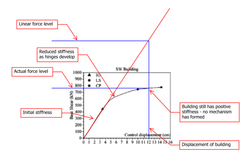
I continue to be confused about this assumption that buildings need to form mechanisms and need to stop attracting lateral load. A "mechanism" to me means that the building has lost stability (the most famous mechanism being the soft-story mechanism). That is definitely not a necessary or desirable trait in seismic design. The "reduced" seismic loads come from the idea that some elements will yield, therefore the overall building stiffness reduces as compared to its initial stiffness. The "reduced" seismic force is because at a certain displacement level, there would be one force associated with the initial, stiffer system, but the actual force of the softened system is less than that. This can be achieved without a mechanism occurring.
-
1
- #42
chris3eb said:If the actual seismic loads don't cause any plastic hinges to form, then each element remains elastic (and not overstressed) for the actual seismic loads?
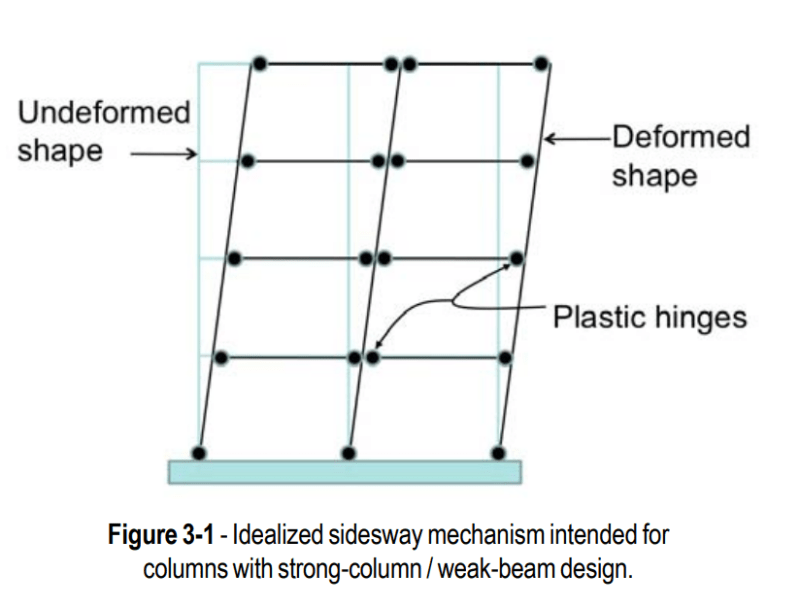
That's pretty much the polar opposite of what I'm saying. For a whole building VLFRS mechanism to form a plastic hinge has to form somewhere. Usually it takes a bunch of them to get the job done. See the the first snip below taken from one of NEHRP's seismic design guide.
chris3eb said:So then why would looking at reduced seismic loads be a problem?
It's only a problem when a whole building VLFRS mechanism fails to form. That, because if such a mechanism fails to form then the stiffness of the VLFRS system does not drop to zero and it continues to attract additional seismic load. A building can indeed dissipate all of the seismic energy imparted to it without forming a whole building VLFRS mechanism and some methods of seismic design take that approach. That's not the case with our conventional ELF/R-Value method however which is rooted in capacity design principles.
chris3eb said:Individual elements can go plastic at different times and reduce the seismic demand to the entire structure (vs if everything stayed linear). This is where the reduced demand comes from - not because a stress-strain curve of the building as a whole goes perfectly plastic.
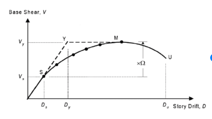
I disagree. See the second clip below which pertains to the overstrenght factor. That factor is there to allow the structure to reach the point of initial plasticity, push through strain hardening and all that jazz, and ultimately form a whole building VLFS mechanism.
chris3eb said:Here are some pushover curves on a frame/building level - they begin to soften as plastic hinges form, but they never go completely flat or negative and if they did, that would be a problem.
The reason those graphs take that form is because pushover curves represent monotonic, static loading conditions. Or, more accurately, loads increased monotonically and slowly enough that they approximate a static loading condition at any one point in time. As I mentioned at the top, the only reason that we can do the voodoo that we do with seismic is because seismic loads are cyclical and inertia based. Neither of those features are present in a pushover analysis (or test).
chris3eb said:Obviously for KootK's example of a cantilever column, forming a hinge is bad because it forms an instability, but that isn't universal
It's quite universal, I assure you. Capacity seismic design requires the formation of a whole building VLFRS mechanism which, by definition, is an unstable condition under static, non-inertial loading. The cantilever column example is merely the simplest possible example of that which is why I chose it for illustration purposes.
Wind loads are an external pressure applied to the structure. The wind pressure is same regardless of the structural response. If the building is responding elastically or if some member (like a girt for example) begins to yield, the wind pressure remains the same in either case. In other words, the load is independent of the structural response. Seismic loads on the other hand, are inherently based on the characteristics of the structure itself.
I hope this answers the original question, because I think the question itself is a bit open to interpretation.
I hope this answers the original question, because I think the question itself is a bit open to interpretation.
chris3eb said:I continue to be confused about this assumption that buildings need to form mechanisms and need to stop attracting lateral load. A "mechanism" to me means that the building has lost stability (the most famous mechanism being the soft-story mechanism). That is definitely not a necessary or desirable trait in seismic design.
Note that soft story mechanism is not a problem because it would be unstable under static, non-inertial loads. Rather, it's a problem because it concentrates plastic strain in too few locations such that those locations take the kind of pounding that winds up causing shear failures, rebar buckling etc. We seek a whole building mechanism precisely because it distributes plastic hinge formation more uniformly throughout the structure.
chris3eb said:The "reduced" seismic loads come from the idea that some elements will yield, therefore the overall building stiffness reduces as compared to its initial stiffness. The "reduced" seismic force is because at a certain displacement level, there would be one force associated with the initial, stiffer system, but the actual force of the softened system is less than that. This can be achieved without a mechanism occurring.
It can as I acknowledged in my previous post which you probably haven't seen yet.
KootK said:A building can indeed dissipate all of the seismic energy imparted to it without forming a whole building VLFRS mechanism and some methods of seismic design take that approach. That's not the case with our conventional ELF/R-Value method however which is rooted in capacity design principles.
-
1
- #45
There is a big difference between plastic design and seismic design.
In general,
For wind, we can design to the limit where plastic hinges form under the ultimate wind load. The building is meant to be fully serviceable after the event.
For Seismic, we design for plastic hinges to form well below the full seismic load/sway. We then allow significant sway after these hinges form to absorb the remainder of the building sway. The building is not meant to collapse under this final condition, but is not expected to be serviceable thereafter and will normally need to be demolished.
-
1
- #46
KootK said:If a structure has it's seismic load reduced by an R-value but does not form a mechanism under the associated seismic event, I would say that those loads were erroneous.
I think this is similar to a discussion we had about reinforced concrete sections a while back. With a reinforced concrete section, the strength is determined by assuming the steel yields and a classic stress block is formed. It's important to know that your reinforced section is capable of reaching this capacity, but under any given loading scenario, the steel may not yield, and that is ok.
I think the ELF seismic design concept started with the idea that the largest load that could occur would be controlled by a mechanism forming, so it's important for that mechanism to conceptually be able to form. But under any given earthquake scenario, the mechanism doesn't need to form. I *think* it's fair to say you can go a little further and say that under any given design level earthquake the mechanism shouldn't form, but I may have to think about that a little more.
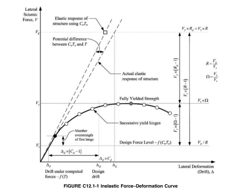
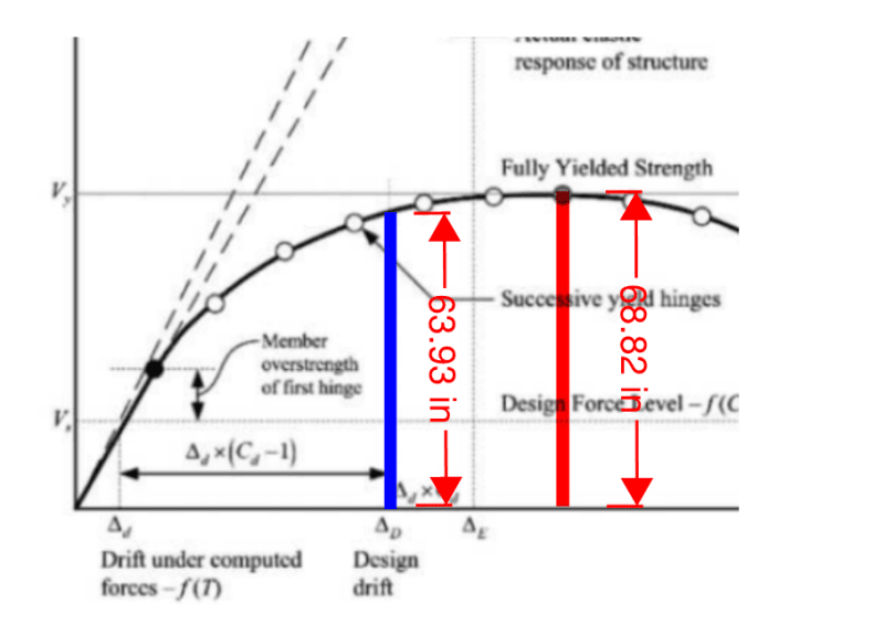
Here's a graphic from ASCE 7 which shows a point of "Fully Yielded Strength" beyond where it shows either the design drift, ΔD or the actual drift, ΔE. Assuming we are in agreement that the "Fully Yielded Strength" is the moment when the mechanism forms, then in this figure they are implying that no mechanism has formed for this design earthquake, but you are still able to use ELF with R and Ω.
With typical ELF design, in my experience, you are following the prescriptive requirements of the code and making sure your members are stronger than the seismic demands. I think the prescriptive requirements: strong-column weak beam, items with overstrength and redundancy factors, capacity designed elements cover everything you need, or the code kicks you out of ELF to a more advanced analysis. I don't think there is an extra check to make sure your beams or columns actually hinge under any given loading because they don't have to hinge under any given loading, they just have to be able to hinge if you were to keep pushing them to the edge.
chris3eb said:I think this is similar to a discussion we had about reinforced concrete sections a while back. With a reinforced concrete section, the strength is determined by assuming the steel yields and a classic stress block is formed. It's important to know that your reinforced section is capable of reaching this capacity, but under any given loading scenario, the steel may not yield, and that is ok.
The absolutely massive difference being that the magnitude of the load in that example is not dependent upon the yielding of the rebar as the magnitude of the load on a VLFRS is dependent upon the development of a mechanism.
chris3eb said:Here's a graphic from ASCE 7 which shows a point of "Fully Yielded Strength" beyond where it shows either the design drift, ΔD or the actual drift, ΔE. Assuming we are in agreement that the "Fully Yielded Strength" is the moment when the mechanism forms, then in this figure they are implying that no mechanism has formed for this design earthquake, but you are still able to use ELF with R and Ω.
I disagree. The load level reached at ΔD basically IS the mechanism load level for all intents and purposes. It's, what, 95% of the way there? If anything, I feel that supports my perspective.
chris3eb said:I don't think there is an extra check to make sure your beams or columns actually hinge under any given loading because they don't have to hinge under any given loading, they just have to be able to hinge if you were to keep pushing them to the edge.
Every time that you, as the designer, choose to design a VLFRS element for a seismic force reduced by the R-Value, that's you deciding that your VLFRS system is to form a whole building mechanism. Or, at least, it should be.
Consider playing chess with me on the Social Chess app at iTunes. Same handle. Fear not, I suck.
HTURKAK
Structural
- Jul 22, 2017
- 3,366
The short answer is NO!!!!
But you are free to choose elastic or plastic design methods as long as the structure remains elastic under design wind loads..
There are 46 replies and i could not look them..
The following doc. is useful to see or refresh the knowledge the behavior of structure under seismic vs wind loading ...
@chris3eb: I've got one more, long shot persuasion play to lay down on this whole building mechanism thing.
As you know, one of our ASCE7 lateral system option is a dual shear wall / moment frame system. Add the 25% moment frame to the shear wall, get some yummy rewards. There is often, however, confusion about how that works. The purpose of the moment frame is not to help with seismic demand during a seismic event. Rather, the purpose is to stabilize the building after the seismic event at a point in time when:
1) The building may be seriously out of plumb.
2) The building may exist at, or near, a a lateral deformation state corresponding to its whole building VLFRS mechanism.
3) People are still trying to shuffle out of the stair shafts to safety.
KootK - I am with you.
At a high level, if we are designing our building structures to behave inelastically during wind events- we are...dumb. If I want my "paper clip" building going plastic and deforming during my design wind event -- I feel like something is intuitively wrong. I want my building to snap back and be ready to roll for another gust.
I understand LRFD and Capacity Design. I respect it. And I am a fan of it -- especially when it describes the actual failure limit state of a system quite well (like in reinforced concrete design, or when ductility is important to consider in seismic detailing).
But tell you - this infatuation with bringing everything to a pure capacity limit state for all systems for all reasons, is something that I do not love. It divorces us from our intuition and, honestly, generates lots of confused engineering students.
So, when I look at the OP - I agree with KootK's sentiment: our design philosophy should be to keep the steel behaving elastically during wind events.
But after the most recent change in ASCE7 (to move wind loads into the ultimate level)... I suppose I'm not even sure of ASCE's intent anymore. Again, another instance of "unnecessary LRFD" robbing an engineer of his intuitive feel of a structure!
"We shape our buildings, thereafter they shape us." -WSC
MJB315 - I'm a little confused by some of your statements there.
LRFD and capacity design are not the same thing. You can design a building using ASD but you still have to use capacity design. Capacity design, as I understand it, is simply ensuring particular behaviors by designing certain components and connections to match the capacity of the member they are connecting. Using ELF, the capacity design locations in the building are prescriptive and not dependent on LRFD or ASD design.
I'm also not sure how LRFD removes the intuitive feel of the structure. Again, whether using LRFD or ASD, I still run an elastic analysis which will show comparable behavior between the two. At their core, the only difference is the statistical allocation of uncertainty. LRFD splits it between the variability of loads and the variability of the material. ASD lumps it all into one. They have little to do with the elastic behavior of the structure, just determination of acceptability of individual members. After all, I'm still going to base serviceability on good ol' D+L.
And the change in ASCE 7 wind provisions is virtually nill for most structures. Pre 7-10, we used 50 MRI and arbitrary importance factors to scale the wind load and applied 1.0W to ASD and 1.6W to LRFD. 7-10 and after, we shift the MRI to create a more uniform reliability rating (beta factor or some such - the commentary has a good explanation on it) across all structures as compared with the arbitrary factors and it becomes 0.6W for ASD and 1.0W for LRFD. For most RC2 structures, the variation in wind load applied in the analysis between 7-05 and 7-10 was something like 2%.
By the way - totally on board with what KootK is saying (nice to see you back, by the way)
@KootK
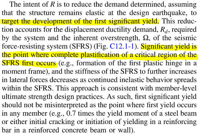
Here are a few more snips from the ASCE 7 commentary. First, from C12.1 (page 544):
And here's from the next page:
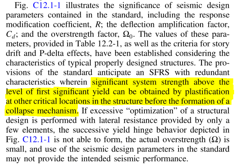
The first snip is saying that the concept of R and Ω is based on the structure reaching its "first significant yield." The second snip is saying that there is still strength gain after the first significant yield before you form a collapse mechanism.
Let's get some terminology out of the way. The code snip above is mentioning a "collapse mechanism" which I would say is when the strength drops to zero, or to some prescribed lower-bound (often times 20% of initial yield strength). Based on what you have been saying, I think the mechanism that you are talking about is when no additional strength can be gained. On the figure above, the collapse mechanism may be the last dot, or the graph just stopped before it got there. And I think the mechanism you are talking about is the gray "fully yielded strength" dot. But based on my reading of these two code snips, R is only based on reaching the point of first significant yield - and it can't be the fully yielded point, since it says you still gain strength afterward.
I also disagree with the claim that the graph is 95% of the way to the first significant yield. Looking at the deformation axis, because force is a function of deformation, it clearly isn't close to 95% of the way there. And even if it was, it's still to the left of it. If you need to go beyond that point for the methodology to be valid, then how sloppy would it be for that graph to show it to the left?
Finally, I wonder what your thoughts are about what happens if there is an earthquake that is half as strong as the design earthquake? How does that fit into your framework?
Here are a few more snips from the ASCE 7 commentary. First, from C12.1 (page 544):

And here's from the next page:

The first snip is saying that the concept of R and Ω is based on the structure reaching its "first significant yield." The second snip is saying that there is still strength gain after the first significant yield before you form a collapse mechanism.
Let's get some terminology out of the way. The code snip above is mentioning a "collapse mechanism" which I would say is when the strength drops to zero, or to some prescribed lower-bound (often times 20% of initial yield strength). Based on what you have been saying, I think the mechanism that you are talking about is when no additional strength can be gained. On the figure above, the collapse mechanism may be the last dot, or the graph just stopped before it got there. And I think the mechanism you are talking about is the gray "fully yielded strength" dot. But based on my reading of these two code snips, R is only based on reaching the point of first significant yield - and it can't be the fully yielded point, since it says you still gain strength afterward.
I also disagree with the claim that the graph is 95% of the way to the first significant yield. Looking at the deformation axis, because force is a function of deformation, it clearly isn't close to 95% of the way there. And even if it was, it's still to the left of it. If you need to go beyond that point for the methodology to be valid, then how sloppy would it be for that graph to show it to the left?
Finally, I wonder what your thoughts are about what happens if there is an earthquake that is half as strong as the design earthquake? How does that fit into your framework?
Hey Pharm,
I understand that cognitively - the two methodologies lead to a similar result. And if you live with LFRD, your gut eventually aligns with it. And our buildings are tailored to their importance to society. And it probably cognitively makes more sense to cook in the return period into the meteorological cubby of the approach (V) than mushing it in with a somewhat clunky importantance/risk factor. And that ELF is a clever way to allow us humans to use simple linear/elastic analysis methods (which balance easy-to-use forces) to model inelastic behavior (which really needs us to keep track of accelerations, which is a nightmare) by using R and Cd factors (which are clunky) to bridge the gap. I'm with you.
The tricky thing is, it does take a lot of experience to start to keep all this rationale clean. And I have found that there is something about the wicked web that we have all weaved that makes it difficult to educate young engineers. Wind speed, no longer means wind speed. And for every student that internalizes the statistical rationale behind LRFD - I run into five students who are still fuzzy on M/S.
I have rejiggered our department's coursework to basically stomp out LRFD until Week 10 of our steel design class. There is just something about ASD (which is yes, still based upon capacity design) that allows young humans to better onboard onto our profession. I have ended up with students able to assess grocery store roofs from a standing start with ASD, instead of suffering through glazed over looks with 1.2D+1.6L. Only after the ASD tree trunk is planted, do I feel like an engineer talks shop like an engineer. LRFD just grows like a "Week 11" type branch ...which rounds second base into Concrete Design.
Now, I didn't read through this entire thread before responding...but after a good skim, I felt like two things were happening:
1. People were getting all 1.2D+1.6L-plastic hinge-ultimate wind speed'd...and loosing track of some good ol' M/S fundamentals. (But again, forgive me if I jumped the gun without reading...this is apparently a sore subject for me), and;
2. I too was happy to see KootK back on posting. I saw his appeal to be backed up, and I dropped my sandwich and said OK I AM ON IT!
"We shape our buildings, thereafter they shape us." -WSC
And ok, I've now actually read through the thread and see where it went.
I'll just land on a LRFS should be designed to remain elastic during wind events.
Could you nudge it a bit further and keep collapse at bay by keeping plastic hinges contained (or mostly contained) within the beams, sure. Probably shouldn't march down this path though.
Seismic design is a different animal.
"We shape our buildings, thereafter they shape us." -WSC
chris3eb said:Let's get some terminology out of the way.
I believe that the whole building VLFRS collapse mechanism is represented by the grey dot because:
1) That is the point on the curve where the VLFRS capacity is at a maximum and;
2) That is the point on the curve where the VLFRS stiffness goes to zero and then becomes negative.
chris3eb said:R is only based on reaching the point of first significant yield - and it can't be the fully yielded point, since it says you still gain strength afterward.
I disagree with your inference. I feel that you're putting the horse before the cart. It isn't the case that R is based on first yield but, rather, that first yield is based upon R. This is the "design" in our seismic design process. We give our members sufficient pre-yield strength such that the displacement ductility required of them is not exceeded.
R itself is defined as [ Omega x Ve / Vy ], with Vy being the load at which the whole building VLFRS mechanism forms. As such, R is predicated upon the existence of a whole building VLFRS mechanism forming.
chris3eb said:I also disagree with the claim that the graph is 95% of the way to the first significant yield. Looking at the deformation axis, because force is a function of deformation, it clearly isn't close to 95% of the way there.
I was speaking of the ratio of the length of the red line to the blue line as shown in the clip below. It measures about 93%.
chris3eb said:And even if it was, it's still to the left of it. If you need to go beyond that point for the methodology to be valid, then how sloppy would it be for that graph to show it to the left?
It's not sloppy but, rather, imprecise. Everything in seismic design is imprecise. This particular imprecision is rooted the equal displacement principle that underpinned Paulay's original formulation of capacity seismic design way back in the 70's.
chris3eb said:Finally, I wonder what your thoughts are about what happens if there is an earthquake that is half as strong as the design earthquake? How does that fit into your framework?
That would merely involve:
3) Traversing the graph only part of the way up to Vy and;
4) Mobilizing less displacement ductility than we believe to actually be available.
Settingsun
Structural
Do you mean use ultimate design loads with elastic section modulus?MJB315 said:I'll just land on a LRFS should be designed to remain elastic during wind events.
If so, I'd be interested to hear if this is how the major US design software handles it.
steveh49 said:Do you mean use ultimate design loads with elastic section modulus?
If so, I'd be interested to hear if this is how the major US design software handles it.
No, in doing your design checks, you would still use the limit states prescribed by the codes and design standards. So if you were using LRFD and the limit state called for a plastic section modulus - you'd of course still roll with that as your red line. If you were designing with AISC360-16, and still opted for ASD design...you'd still use the same limit state. You could always opt to be more conservative and use the elastic section modulus if you wanted to, I suppose.
But realize that even if you use "ultimate design loads"...your actual demand stress in your member is probably still in the elastic range.
Say you were designing an Arby's in Long Island in New York State. The building would be a Risk Category II building. If you loved roast beef, you may opt for a higher importance factor - but the code minimum would be Risk Category II.
The building code (well, ASCE7-16) would ask you to design for an ultimate wind speed of 120MPH. Say you opt to design using an "ultimate" approach... and design flexural member (a compact, well-braced, W-shape) made using steel with a yield strength of 50 ksi, right to the limit using a Phi factor of 0.9 and to its yielding limit state (using the plastic section modulus). Well, when the hurricane comes and hits this Arby's in Long Island - the member designed using an "ultimate" approach and the "plastic" section modulus...would still behave in it's elastic range. Which is good! Let's keep our wind lateral force resisting systems operating in the elastic range.
![[2thumbsup] [2thumbsup] [2thumbsup]](/data/assets/smilies/2thumbsup.gif)
But this "ultimate vs. elastic" (as if they are different) issue keeps creeping up in my discussions. I keep coming back to a sinking feeling, that there is something about the way that our design methodology works obscures something from us. The Demand>Capacity checks are worked out analytically in a statistically pure way - but many of us get a tad more confuzzled because of it when it's slathered with load factors.
I'm not quite sure what to do about it - it's unlikely we're going to spawn a new generation of engineers with the intuition of someone who learned on the 7th-8th-9th editions of AISC and are great Revit Drivers - but I just find that the card rules to our little game are hard for new comers to grasp well.
Anyway, I don't mean to derail this thread by answering a question that wasn't really asked. I just don't like the shift to "ultimate level wind", among other things, because I think it clouds our profession somewhat. I'll do what I can in this neck of the woods to clear the air, and we can move this to a separate thread if need be.
"We shape our buildings, thereafter they shape us." -WSC
CELinOttawa
Structural
Extremely interesting that this came up in today's ATC online webinar "ATC Design Guide 3, Serviceability Design of Tall Buildings Under Wind".
Reflected my comments. Openly discussed that ductility is a reasonable approach, and a likely future in wind design. "Probably being too conservative by trying to keep these buildings elastic".
The course was recorded. I'm sure ATC will make it available. Bill Baker, Larry Griffis, and Peter Irwin's comments were all very interesting regarding buildings that have had isolated high wind issues.
The conclusion was that we need to be more careful with narrow and tall buildings for serviceability, not for ULS.
Anyone work on one of those new "blade" structures in New York? Narrow face to height of 1:25 sounds like a tremendous challenge without allowing for some energy dissipation; it is active damping?
CELinOttawa said:Anyone work on one of those new "blade" structures in New York? Narrow face to height of 1:25 sounds like a tremendous challenge without allowing for some energy dissipation; it is active damping?
I've done a little, peripheral work on similar structures. Many, out of necessity, take the form of [CONCRETE CORE + OUTRIGGER]. As such, where passive damping is employed for vibration control, it often runs along the lines of:
1) Plasticity in some of the outriggers and;
2) Not the formation of a whole building VLFRS mechanism which would involve plastic hinge formation in all of the outriggers as well as the core.
It has certainly never been my intent to argue that wind VLFRS cannot develop local plasticity so long as a full blown mechanism is not developed. So, in that, I think that we agree.
CELinOttawa said:Openly discussed that ductility is a reasonable approach, and a likely future in wind design.
My personal view is that Performance Based Wind Design is likely the future for very tall buildings. As with seismic PBD, that will include the allowance for reasonable excursions into the inelastic range in local elements.

- Status
- Not open for further replies.
Similar threads
- Question
- Replies
- 3
- Views
- 7K
- Question
- Replies
- 7
- Views
- 8K
- Replies
- 8
- Views
- 769
- Replies
- 3
- Views
- 824
- Locked
- Question
- Replies
- 0
- Views
- 2K
