Continue to Site

Eng-Tips is the largest engineering community on the Internet

Intelligent Work Forums for Engineering Professionals

  • Congratulations waross on being selected by the Eng-Tips community for having the most helpful posts in the forums last week. Way to Go!

are these these geometrically the same?

Status
Not open for further replies.
Replies continue below

Recommended for you

I convinced myself that they can't be the same because one locks more degrees of freedom than the other. Attached is a new example that has locks equal degrees of freedom for both cases. Are these geometrically equivalent? I'm sure this seems silly but I'm trying to test how well I know this stuff.

Thanks
 
 http://files.engineering.com/getfile.aspx?folder=611d4d87-4bc2-4af6-885c-7f36fd57161d&file=gd&t_question.PNG
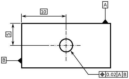
Dang, I can't get the attachments to show up for some reason. Basically the pictures are two rectangles with basic height and width dimensions. One rectangle has datum A on the rear face. Datum B on bottom edge with flatness callout of .030, the two vertical edges have perpendicular control of .030 relative to A and B, and the top edge has parallel control of .030 relative to A and B. The other rectangle has datum A and B in the same locations but an all around profile tolerance of .030 relative to A and B.

My initial post did not have datum B for the profiled rectangle, however I find it locks only 3 degrees of freedom where the other rectangle locks 5 degrees of freedom.

Hopefully that made sense.
 
Stop putting special characters in the file names. Then the attachments will download.
 
Greg2835

At first glance: you cannot use BSC dimensions with parallelism and perpendicularity to control the size of the block. So your comparison question is somewhat moot.

The relationship between Datum A and the top face is not parallelism but is perpendicularity. So the control is not per Standard. From a drafting standpoint, the controls only apply in the view shown. So you should apply the control in the end view. You have taken a reasonable liberty in showing the "perpendicularity" relationship by identifying Datum in the front view. But I assume be block is "square" so other views maybe needed to confirm my assumption.

In the profile example, Datum B is included in the profile tolerance. Although technically possible ,it is not good practice to have a feature related to itself.

Certified Sr. GD&T Professional
 
mkcski

You're right, basic dimensions cannot be used for parallelism and perpendicularity (smacks forehead). That answers that question then. You're statement about the profile example leads me to another question. Let's say I want the profile "window" of .030 around the part, but I want the part to be inspected where the part is "laying" on datum A and "clocked" by datum B. In the attached picture I drew the .030 window (actually .15 but made it bigger for clarity) and the profile of the actual part. If I "clock" this part so feature B is horizontal then the bottom edge will fall outside of the window and will fail inspection (which is what I want). This was my reasoning for adding datum B to the profile FCC. Is this appropriate or is there a better way of doing this? Still trying to get my head around this stuff.
 
 http://files.engineering.com/getfile.aspx?folder=704c89ca-b6d2-47e1-9688-da7941073689&file=Capture.PNG
greg2835

Datum B clocking is not needed. The all-around symbol implies a BSC 90-degree rectangular relationship between the four surfaces, so clocking is not necessary. See 2009 Section 1.4, paragraph (j) By adding Datum the 4 surfaces collectively (as a group) are to be perpendicular to the datum feature.

Certified Sr. GD&T Professional
 
Right and I understand that Datum B clocking is not needed. But let's say I want the part to be inspected such that feature B is clocked (see the attached). In my previous attachment if I were to clock B horizontal the edge would have fallen just outside the profile window and I would want that part rejected, so using |profile|.030|A| does not accomplish what I am after.
 
 http://files.engineering.com/getfile.aspx?folder=a3e03e45-7208-4dea-bfd0-4df099112fbe&file=Capture2.PNG
greg2835,

The tolerance scheme on the right side of your first downloadable attachment "gdt_question.PNG" seems perfectly valid and reasonable to me. Note that the tolerance zone for datum feature B will be centered on the datum plane, so half of it (.015) will be unavailable. If you want the same .030 tolerance zone available for all four surfaces, you will have to adjust things a bit. There are several ways to accomplish this in ASME Y14.5-2009.


pylfrm
 
greg2835

To accomplish your goal: I recommend you remove the Datum B feature from the profile control. You would remove the all-around symbol and apply the profile to the three remaining sides - I suggest using the "between" symbol (line with arrows on both ends). I would then add flatness to datum B to control its form. The FCF would have A then B datum sequence.

Certified Sr. GD&T Professional
 
pylfrm,

that's exactly what I was afraid of. Wasn't sure if there was something I didn't know in the standard that "shifted" the window for cases like this but I guess that could get rather confusing in other circumstances.

mkcski,

perfect, that makes sense. I guess the way I look at it is first qualify datum B and then profile the edges relative to B. genius
 
Greg2835

Of note: it is NOT good practice to let an inspection method determine the tolerancing schema. Design intend - I call it "part function and fit-up" - should be the driving focus. Input from Mfg an QA must be considered - ya gotta make the part at a profit - but the part must "work" in the end.

Certified Sr. GD&T Professional
 
Couldn't agree more, mkcski. Right now I'm just coming up with brain teasers to get my head around this stuff. My thought was if I wanted this part to fit in an assembly where feature B is mated to another surface and the remaining edges must fit within a given tolerance window.
 
Ask away my friend. The would needs more GDT "specialists". Do you plan on taking the Certification test at some point?

Certified Sr. GD&T Professional
 
Thanks mkcski, and yes that is my plan. So far this site has been a tremendous help so I'm sure you will see more questions like this on here.
 
Status
Not open for further replies.

Part and Inventory Search

Sponsor