Eng-Tips is the largest engineering community on the Internet

Intelligent Work Forums for Engineering Professionals

AS3600 Torsion

Status
Not open for further replies.

Trenno

Structural
Feb 5, 2014
831
0
0
AU
All,

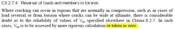
When have you guys ever reduced Vuc to 0 by adopting the following clause?

Vuc_us0usl.jpg


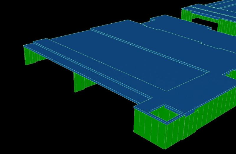
My situation: compatibility torsion on an internal T beam, from elastic uncracked analysis, is higher than 0.25PhiTuc and thus requires transverse steel to resist this torsion.

Now this torsion could potentially cause cracks (45 deg to long. axis) in the compression zone of the section and thus why I'm wondering whether to ignore the concrete contribution in shear?

Ignoring this moment and assuming cracking/redistribution of load to the adjacent slabs has occurred also leads me to believe that Vuc should be 0.
 
Replies continue below

Recommended for you

Designing the beam to the torsion section of the code results in double the shear density (Asv/s) required as opposed to the converting the torsion moment into a shear across the web of the beam.

In a 2400 x 500 beam, the total loss of Vuc is very significant. My engineering judgement (very green) tells me this beam does not need 6 legs of N12 @ 100 c/c.

 
By cracking at the top of the flange/web junction and thus relieving the torsion moment as positive bending into the slabs?

 
Yup. The load will redistribute and go where it's been detailed to go. If it's an insitu banded slab you could set your torsional stiffness to zero and the structure would still be stable with correctly detailed ligs and slabs.
 
Yeah, I've ended up designing the beams such that the torsion is added to the shear force. (This is in RAM, "as shear" option). I have modelled the beams without any torsional stiffness, but I think I'll still provide minimum torsion ties.

It's just when RAM sees torsion greater than min reo it automatically takes Vuc = 0. I emailed one of the senior directors who looks after Concept and he explained it quite well.

I'm assuming the transverse shear leg spacing rule of D or 600 won't apply to the torsion clauses, as the outer "loop" will do all the work. Thoughts? Providing 6 legs every 300mm seems overkill.

Just for completeness the beam in question is shown below.

element_j8r52e.jpg
 
And for anyone who is interested....

Hi Trent,

The “as shear” option assumes that the torsion is resisted by a linearly-varying vertical shear across the shear core.

For a rectangular beam with linearly-varying bending stress, the section modulus used to calculate the bending stress is bh^2/6; similarly for linearly varying vertical shear stress across a rectangular shear core, the “torsion section modulus” is b^2h/6. That is where the “6” comes from.

In “as shear” the peak torsion shear stress is added to the standard shear stress to determine a total shear stress “demand”, which is then applied to the entire shear core to become a shear force demand. I hope you can see how this represents a conservative mechanism to transfer the torsion. The primary caution I should note about this method is that it implicitly assumes you have 2-legged links (if any links) with the legs near the beam faces (so there can be a shear couple with shear up on one face and down on the other).

Regarding the closer spacing of links when using “as beam” torsion design – I assume this is due to minimum spacing criteria and not strength.

I suggest you look at the situation to determine what the actual beam behavior is. For example, if you have a beam that is supported by a column that is not at the beam center, you are always going to get high “torsion” (relative to the beam centroid) near the column, although the stresses in the beam are primarily (eccentric) shear.

One other item to note – have you tried releasing the torsion stiffness in the beams? (you will still get some torsional stiffness because of the vertical stiffness). A standard approach for “compatibility” torsion is to release the torsion stiffness and use minimum torsion links.

Hope this helps.

-Allan

Allan Bommer, PE, FACI
Senior Director, Product Engineering


Cheers mate. I have had some funny experiences with that torsion design as well, particularly for internal band beams. I use the wood-armer, then audit the first cross-section in the design strip away from the support and it throws in heaps of extra reo.
 
My understanding is that Wood-Armer torsion design does not apply to beams, only elements such as two way flat plates.

What's your take on this...

I'm assuming the transverse shear leg spacing rule of D or 600 won't apply to the torsion clauses, as the outer "loop" will do all the work. Thoughts? Providing 6 legs every 300mm seems overkill. IS there any chance for me to curtail down the number of legs needed throughout the length of the beam?


Status
Not open for further replies.
Back
Top