li0ngalahad
Structural
Hi all,
I had a discussion with a colleague about the requirements for boundary elements in limited and moderately ductile shear walls. According to the code, boundary elements are required wherever the peak stress in the wall exceeds 0.15 f'c. The debate revolves around which earthquake load should be used for this check: the elastic load (mu=1, Sp=1) or the design earthquake load (mu=2; mu=3 and Sp=0.77; Sp=0.67). The code states, "The stress referred to in Item (b) shall be calculated using the design action effects for the strength limit state, a linear-elastic strength model, and the gross cross-section properties of the wall." This seems to imply that the reduced forces should be used, not the elastic forces, which has always been my understanding.
My colleague noted a potential issue: if a limited ductile wall requires boundary elements because the stress exceeds 0.15 f'c, the structure could be reclassified as a moderately ductile wall system. This reclassification would significantly reduce the earthquake design actions, potentially bringing the stress below 0.15 f'c, and thus not requiring boundary elements. This creates a paradox where a shear wall with higher assumed ductility would require fewer boundary elements than one with lower assumed ductility, which doesn't seem logical.
This raises the question of whether we should assess this stress based on the fully elastic response (mu=1, Sp=1), similar to the process when checking if any portion of the wall experiences tension (which requires designing the wall as a column). The problem is that the code specifically advises against this!
Another point to consider, which could help resolve the above paradox, is the interpretation of clause 14.7.1 (b), which states, "Moderately ductile structural walls shall conform with Clauses 14.6 except [...] in Clause 14.6.2 all vertical reinforcement in boundary elements shall be restrained in accordance with Clause 14.5.4 irrespective of the calculated compressive stress." This could be interpreted so that boundary elements need to be detailed at all levels, at all wall ends, corners, and intersections, even where compression forces are minimal.
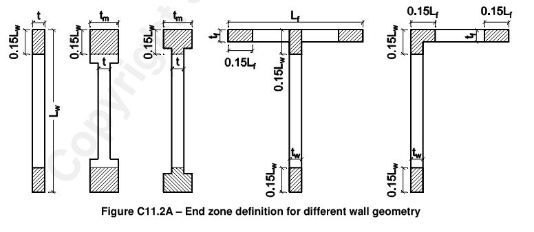
I've always interpreted this clause to mean that, for moderately ductile walls, detailing according to 14.5.4 applies without distinguishing between 0.2 f'c and 0.15 f'c, but the boundary element zone would still be designed only as the zone where stress exceeds 0.15 f'c. However, this discussion has left me uncertain, and I wonder if the clause implies that boundary elements are required everywhere, even for stresses below 0.15 f'c. If so, what should be the length of the boundary element if no stress check is required? Should it be the greater of 0.15 Lw and 1.5 bw, as per the critical tension zone for minimum longitudinal reinforcement? The code and commentary don't seem to specify this at any point.
I'd appreciate your views on this and how you interpret these clauses in the code.


