Continue to Site

Eng-Tips is the largest engineering community on the Internet

Intelligent Work Forums for Engineering Professionals

  • Congratulations GregLocock on being selected by the Eng-Tips community for having the most helpful posts in the forums last week. Way to Go!

AS4100 Beam design confusion 1

Status
Not open for further replies.

Ilight

Civil/Environmental
Dec 2, 2018
10
Hey everyone:

So I've always been told to assume the rotational restraint factor kr as 1 for the effective length calculation. Then I had a look in AS4100, apparently it is associated with lateral rotation of the member.

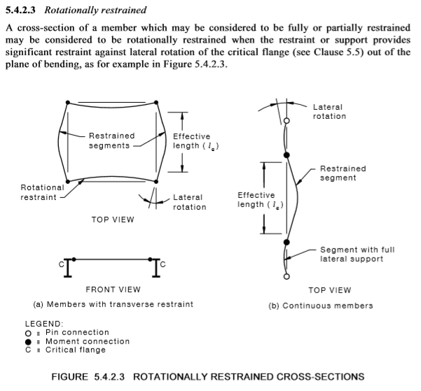
My question is how are these restraints provided? In C5.4.2.3, it seems to say that in addition to a segment being FF, PP and etc, you have to apply another set of restraint to prevent lateral rotation.

Are these restraints applied along the segment or only at the ends of the segment?
1_rggqpp.png


Cheers!
 
Replies continue below

Recommended for you

The rotational restraint is at the F or P cross-section. It's analogous to ideal (Euler) column buckling: a pin-pin column has effective length equal to the distance between pins because the half-sine buckled shape is over that length. If the column has rigid-rigid ends (rotationally restrained), the half-sine is shorter because there are two inflection points along the column length in the buckled shape as it has to 'straighten' at the restrained ends.

For flexural buckling, the 'column' is the critical flange. For a gravity-loaded beam,the plane of bending is vertical, the buckling direction is horizontal, so you're interested in whether the flange is constrained to remain 'straight' when viewed from above at the F/P section. If so, the effective length is reduced and the buckling capacity increased. An example would be a heavy moment end plate connection to a massive wall.
 
Another practical application is if an adjacent segment has full lateral restraint (alpha_m x alpha_s greater than or equal to 1.0), then you can count that end as applying rotational restraint about the minor axis and take kr less than 1.0.
 
Hi Agent666

By adjacent segment, do you mean for example in F-P-L segment, if F-P has full lateral restraint, I can take P section as rotationally restrained?

Cheers
 
If you mean you have FP & PL segments in a continuous member say, and FP segment has FLR, then PL segment cannot take benifit of the rotational restraint. Table in code only allows k_r reduction for FF, FP or PP segment from adjacent segments (but adjacent segment could have any restraints at the other end (except U obviously because that's not laterally restraining the segment from lateral movement or twist of the cross section)).

However, if the PL segment had FLR, then the FP segment would have rotational restraint at one end from the adjacent PL segment just like figure (b).

Keep in mind in its application that the restraint its talking about is rotation about the minor axis of the beam critical flange (rotation in plan), and not the same as twist of the cross section being restrained by F or P type restraints. Hopefully this is pretty clearly demonstrated by examining figures (a) & (b) for the two practical types/ways of achieving the reduction in the effective length.

For figure (a) type reduction its to do with the EI/L being comparable with the restrained segment (effectively creating continuity).
 
Status
Not open for further replies.

Part and Inventory Search

Sponsor