Eng-Tips is the largest engineering community on the Internet

Intelligent Work Forums for Engineering Professionals

  • Congratulations waross on being selected by the Eng-Tips community for having the most helpful posts in the forums last week. Way to Go!

ASCE 7 Two Stage Seismic Analysis 4

Status
Not open for further replies.

cdowney4

Structural
May 31, 2002
14
US
When looking at the ASCE 7 Two Stage Analysis Procedure, there seems to be an anomaly that bothers me and I'm wondering others opinions/experience. In terms of seismic forces, it seems to me that the two stage procedure can be quite beneficial for the upper level light-framing, but can be penalizing on the lower rigid structure (and foundations).

What bothers me is that I could look at it per 12.2.3.1 (ASCE 7-10) for Vertical Combinations and potentially get an overall lower base shear/overturning on the building, but a higher distribution of forces on the upper levels. Or, I could look at it per 12.2.3.2 as a two-stage and get lower distribution of forces on the upper, but larger overall base shear and overturning for the building.

What I would really want to do is design the lower portion per 12.2.3.1 and the upper per 12.2.3.2. It seems pretty clear that is not the intent of the language of the code, but the practical side of me says that if I took the penalty on the upper framing by just using 12.2.3.1, I have a code-complaint lower portion of the structure with lower design forces. But if I design the upper per 12.2.3.2, all of a sudden that same dsign for the lower portion is not code compliant? How does the lower portion know what design methodology I used or what forces the upper levels were designed for?

In my particular current case, I'm looking at a building that is 4 stories of wood framing over 3 stories of P.T. slabs and concrete shear walls, so perhaps this anomaly is more severe than a single level rigid lower portion.

Am I way off on this type of practical thinking? Even if I am not, perhaps I am just yelling at the clouds.
 
Replies continue below

Recommended for you

Yes I need a better approximation than the ASCE formulas, but I don't want to do too much work. My suggestion was this method thread337-489293 but my coworker said he thought this might be beyond the scope of the formula. What do you think?
 
'not too much work' and 'better approximation' are at odds with each other. A six story building should merit 'a lot of work' if you ask me
 
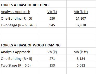
Mike -- this is what my last table was supposed to look like:

base-shears_bjhhp0.jpg
 
These issues remind me of a paper by Ed Wilson. Interestingly it used to be up publicly on his website and now the link is broken. It is a rather contentious article for an engineer if I do say so myself.
Here is the paper Link

Yeah good article, though if he's so concerned about the use of RSM analyses and is a proponent of the FNA method for everything, it isn't overcome by the need for selling more Ultimate level ETABs or SAP2000 licenses obviously [bugeyed].

If they were serious about killing RSM for the betterment of the engineering design community, then make those methods/functions available to the masses and it will drive uptake....... it's behind a paywall essentially at the moment that not too many companies are probably going to buy into for day to day work.

 
Mr. Downey, seems a bit odd to me your base shear for your entire structure differs by almost a factor of 2 between the two methods. Can you share some more of your variables? Which ASCE 7 formula determines your seismic response coefficient? I suppose your results might make sense to me if the limitation of ASCE 7-10 12.8-3 controls: Cs = (SD1 x Ie) / (T x R)
 
Mike, yes I will review and share more detailed results. This particular project has been stalled in the early stages for a while now, but may start heating up again, so a good chance to double-check my quick early numbers. And now it's turned into a podium with three separate buildings on top, so while it's pretty clear to me that the two-stage approach is the right approach, even with a "penalty" on the podium, I always want to understand what drives the results. Stay tuned.

Chris
 
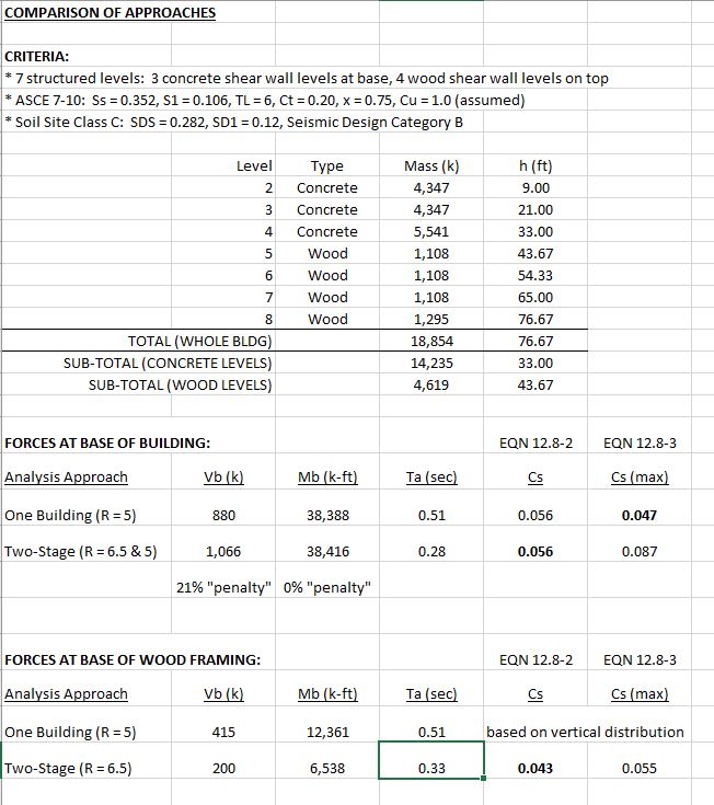
Mike, I will say a few things after taking a closer look at my numbers:

I was incorrectly using Test = Cu*Ta to determine my forces. We do a lot of steel moment frame parking structures, so this is how I generally start my analysis and then verify that the actual period is greater. I'm usually smart enough to make Cu = 1.0 in my spreadsheet when doing stiff shear walls, but was going too quickly.

You are correct that whether or not Cs (Eqn 12.8-2) or Cs-max (Eqn 12.8-3) is controlling can make a significant difference, and obviously is dependent on height and period:
[ul]
[li]
My incorrect use of Test had Cs-max controlling for both methods.​
[/li]
[li]
Using Ta with my condition of 3 concrete levels below 4 wood levels had Cs controlling for the Two-Stage procedure and Cs-max controlling for the Single-Building approach.​
[/li]
[li]
For curiosity's sake, reducing my number of concrete levels to 1 level makes Cs control for both methods.​
[/li]
[/ul]

In the end, for my case, I'm no longer finding much of a "penalty" on the concrete levels with the Two-Stage method. A 20% increase in total base shear, but virtually no increase in overturning. And when looking at just 1 level of concrete, I'm seeing only an 11% increase in base shear, but a 36% REDUCTION in overturning. So, maybe I was wrong all along (don't tell my wife I admitted I was wrong).

Now what I'm starting to wonder is if I really should verify that the 3 concrete levels meet the 1.1 period and 10x stiffness requirements for the Two-Stage procedure. This is what brought you this thread in the first place. You have 2 levels of concrete moment frames and I have 3 levels of concrete shear walls, both below 4 levels of wood. My gut tells me your lower levels will be too flexible and I'm hoping (and was assuming) the opposite for me. I will use RAM Structural System to analyze the the concrete levels so that I can export to their post-tension module, but I still think I would do the stiffness and period checks by hand. The problem for me is that I am not designing the wood levels, and both the concrete and wood levels are at a schematic level right now.

Thanks for making me take a closer look.

Chris

Capture_e6zkfx.jpg
 
Sorry for the delayed response on this. I was on holiday for the last week or so (in WI no less).

mikemike said:
Koot K., I agree with the first half of your post, not sure I follow the second half. What is del?

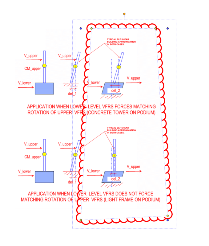
What is del??? I posted explicit pictures of del FFS.

del_1 = the center of mass drift of the upper portion of the building relative to it's own base.

del_2 = the center of mass drift of the upper portion of the building relative to the podium's base.

mikemike said:
It seems to me rotation plays a bigger role on buildings with small footprints and shorter shear wall lengths.

I wasn't speaking to the absolute rotation of any one system versus another but, rather, whether or not the nature of the setup encourages consistent angular rotation between the upper and lower portions of the building. It's the difference between the two, clouded sketches below fundamentally. Were you to shear the base over to one side, does the upper building do that too or just go along for the ride rigid body like?

mikemike said:
Is it your intent to make it harder for tall slender buildings to qualify for 2-stage?

My intent is simply to pursue the truth and to create a procedure that does a good job of capturing the effect that it means to capture. You're correct, though, in that in many instances, it would have the effect of precluding tall buildings from qualifying for the two stage procedure. And I find that to be rational because, in many cases, I don't see tall buildings vibrating to a mode shape with a big discontinuity in it as the two stage procedure implies.

c01_yubp3o.png
 
mikemike said:
Yes I need a better approximation than the ASCE formulas, but I don't want to do too much work. My suggestion was this method thread337-489293: Period of Wood Structure Calculated to Justify Lower Earthquake Loads but my coworker said he thought this might be beyond the scope of the formula. What do you think?

Rayleigh Ritz would have been my recommendation as well. That said, your coworker's concerns are, to some degree at least, valid in my opinion. Without actually answering your question in any definitive way, these are my thoughts:

1) Rayleigh Ritz will have you work out static deflections based on a model of the structure that does account for stiffness variation from floor to floor. Of course, the efficacy of that accounting is up for grabs.

2) Two common ways to discretize the problem include:

a) Discretize the physical structure and develop a continuous/contiguous solution. This is basically regular FEM applied to dynamics and tends to do a good job of stuff with local concentrations of mass and stiffness.

b) Assume a continuous/contiguous -- and gently varying -- structure and instead discretize the solution. This is basically Rayleigh Ritz which does some minimization voodoo on an infinite series representation of the solution.

So it seems reasonable to assume that Rayleigh Ritz does, in some measure, rely on a structure being somewhat uniform or, at the least, gently varying.

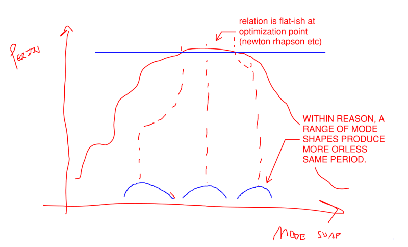
On the other hand, one of the powerful features of Rayleigh Ritz is that, precisely because it is a minimization thing, the solution algorithm tends to be fairly insensitive to whether or not particularly accurate mode shapes are used / developed. At the extrema, the curves being minimized / maximized tend to flatten for a stretch.

3) My own intention for the future is to just let FEM software workout the period for me and use those. That way I'll be relieved of having to somehow know where the limits of appropriateness lie for things like Rayleigh Ritz. I feel that I need to bone up a bit on my understanding of FEM based dynamics to be confident in this however. I've added the book below to my near term reading list for this purpose. Hopefully it gets me where I need to go. I like pretty much everything by Weaver.

c01_c3eqxh.png
 
Koot K. let me know if you need any recommendations next time I know all the spots! I'm in WI

I got you now, if upper portion rotates along with forced rotation in lower portion, it's not a good candidate for 2-stage procedure. Is your thought that because the modal response of the two are tied together, it's unconservative to analyze the upper portion as though it sits on a rigid base?

Your screenshots say VFRS but the text of your first post says LFRS, although I suppose they both have to come along for the del ride either way lol. Just a thought here, but one factor that might be included in your method, perhaps incidentally, would be the ratio of lateral resisting to vertical resisting elements? A tall concrete shear wall structure with few shear walls and a lot of vertical columns would tend to deflect (del) less at the roof in comparison to a tall shear wall structure with few shear walls and few vertical columns. Either way the shear wall dels and rotates at the first elevated floor under the applied load, but as you go up the structure, wouldn't the columns, bent in reverse curvature, tend to resist and straighten out the shear wall for the upper levels? I would expect the concrete floor slabs to have some resistance to the forced shear wall rotation as well.

Would you propose adding to or replacing the current ASCE rules? Seems like a step in the right direction, but I think the 1.1 rule and the 10x rule are good ones too.
 
Mike Mike said:
Koot K. let me know if you need any recommendations next time I know all the spots! I'm in WI

My "spot" this time around was mostly my inlaw's house on Tighigan Lake (Fox River). That's tough to beat this time of year.

Mike Mike said:
Is your thought that because the modal response of the two are tied together, it's unconservative to analyze the upper portion as though it sits on a rigid base?

Sort of. It seems to me that two stage is predicated upon a first mode response that would have a kink in the normal shear building deformation response. Stiff AF up to the transfer deck and then taking off at a more aggressive angle after that. A building who's VLFRS is a concrete shear wall up and down the whole thing simply isn't that in my opinion as I would expect the stiff wall to force a common angular change in the VLFRS the whole way up. I'm less concerned about it bein unconservative than I am with it being hopelessly spurious.

OP said:
Your screenshots say VFRS but the text of your first post says LFRS, although I suppose they both have to come along for the del ride either way lol.

Acronym fail. VFRS = LFRS = VLFRS = shear walls and braced frames and stuff like that.

Mike Mike said:
...but one factor that might be included in your method, perhaps incidentally, would be the ratio of lateral resisting to vertical resisting elements?

I don't see it. That ratio would mostly speak to P-Delta amplification in my mind and I don't see how that would need to be a deciding factor in the whole two stage thing.

Mike Mike said:
...but as you go up the structure, wouldn't the columns, bent in reverse curvature, tend to resist and straighten out the shear wall for the upper levels? I would expect the concrete floor slabs to have some resistance to the forced shear wall rotation as well.

Sure. That would be classic shear wall frame interaction per the sketch below. That said:

1) Shear wall do tend to create uniform story shear racking. This is one of the reasons that they are desirable in seismic situations.

2) Everything is approximate all the time. If we try to rope too much, non-essential stuff into the litmus test for two stage, we'll wind up with something unusable.

3) In my opinion, two stage is mostly for light fame stuff over concrete or steel podiums. I don't feel that two stage is appropriate for the kind of building that would exhibit serious shear wall - frame interaction.

Mike Mike said:
Would you propose adding to or replacing the current ASCE rules?

Probably replacing or modifying. It's difficult to say because I don't really know what went into the development of the metrics that we currently have. Nowadays, I would expect some MSc student to run fifty dynamic, time history models to validate the limits that we use to see what makes sense. And, for all I know, that's already taken place and led to the limits that we have in ASCE. Presently, I simply question the efficacy of procedure that allows buildings to qualify for two stage that, in my opinion, clearly should not.
 
Chris, keep us posted on your 1.1 period check [ASCE 7-16 12.2.3.2 (2)]. How do you plan to "do the stiffness and period checks by hand"? you gonna read KootK's Weaver book? I need to hit up the library myself so I can figure out what KootK is talking about here. "the solution algorithm tends to be fairly insensitive to whether or not particularly accurate mode shapes are used / developed" right, uhhhh... *nods and smiles*
 
MM said:
I need to hit up the library myself so I can figure out what KootK is talking about here. "the solution algorithm tends to be fairly insensitive to whether or not particularly accurate mode shapes are used / developed" right, uhhhh... *nods and smiles*

Smart ass. I'm afraid that there's just no way to dig deep on this without wading into the theoretical. It's basically this, with the sketch below added in the hope that it makes the explanation more palatable.

KootK said:
At the extrema, the curves being minimized / maximized tend to flatten for a stretch.

If you look into the derivation of RR, it's an optimization problem where you're mathematically seeking the extrema which tend to be locations where stuff isn't changing so fast. I have no idea what a Period Vs Mode Shape graph really looks like but, at the same time, I don't think that it matters much as far as this explanation goes. So the method derives its power from the fact that you don't have to nail the mode shape bang on. At the same time, however, you do need be somewhat in the ballpark. The trouble, with respect to this conversation, is somehow figuring out where the fence is at.

C01_nvuat4.png
 
Status
Not open for further replies.

Part and Inventory Search

Sponsor

Back
Top