Continue to Site

Eng-Tips is the largest engineering community on the Internet

Intelligent Work Forums for Engineering Professionals

  • Congratulations SSS148 on being selected by the Eng-Tips community for having the most helpful posts in the forums last week. Way to Go!

ASCE 7 - Wind Design - Freestanding Wall or Fence - Force Coefficient Figure 29.4-1 - Case C

Status
Not open for further replies.

JoelTXCive

Civil/Environmental
Jul 24, 2016
933
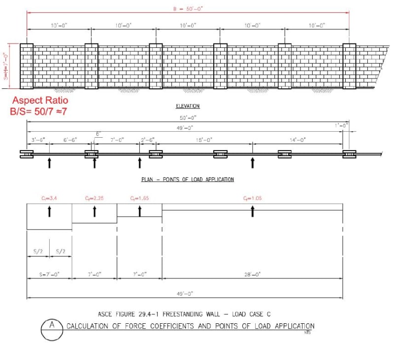
I'm trying to calculate the wind loading on a freestanding brick wall using the ASCE 10 Chapter 29 provisions.

There are 3 load cases that we are required to apply (Case A,B & C).

Cases A&B are pretty straight forward, but Case C seems unnecessarily difficult and confusing.

For this exercise, lets assume I have a 7ft tall wall of 50ft length; and I have columns spaced at 10' O.C.

If I follow the ASCE Figure 29.4-1 rules for load case C, then I will apply point loads at 7ft C-C spacing. (which doesn't line up with my column spacing, so the math gets harder)

See below images, or PDF.

Am I applying the guidelines correct?

Capture_1_rhw2um.jpg


Capture_2_vlmeoj.jpg


Thank you for the input!

 
Replies continue below

Recommended for you

I didn't review it in detail, but yes - that looks correct. In your case, I'd say some amount of engineering judgement is warranted. Perhaps work out an equivalent variable distributed load that's roughly equivalent to the point loads. Or just apply each point load to each panel of the wall - it will yield a conservative result but not overly so, and it'll simplify your math.

The point is to capture the fact that the aerodynamic effects around breaks in the wind flow cause locally increased pressures (just like Zone 5 for C&C for wall pressures), as well as the effects of wind hitting the wall at an oblique angle. If anything, Case C is probably most applicable to a wall like what you have. The others are more for short or at least discreet panels of signs or similar objects. For signs, case A gives you the worst case for the panel framing in a double pole sign, while Case B gives the worst case load in one of the poles of a double pole sign, and torsion in a single pole. Case C is for long walls.
 
For a point load for each wall panel, you'll need to bump them up a little so your area is 7ftx10ft, not (7ft)2.
 
Thank you for the reply Pham. I think you are correct on applying some engineering judgement.

I arbitrarily selected 50ft as my length, which impacts the Aspect ratio; and then effects the final Force Coefficients used for loading.

In reality, I would like to design an infinitely long wall, but that would generate a super-high aspect ratio where you are picking up 4.3 times the load in the perimeter wall panel.

I think I could come up with a way to rationalize my wall design length to maybe ~30ft to get a more rational load value.

 
Status
Not open for further replies.

Part and Inventory Search

Sponsor