Eng-Tips is the largest engineering community on the Internet

Intelligent Work Forums for Engineering Professionals

[ASK]can splitcase pump use vacuum pump as its priming system?

calmwind123

Student
Oct 17, 2024
4
0
0
ID
Hi, i just created account in this forum, because i wanna ask something regarding my project.

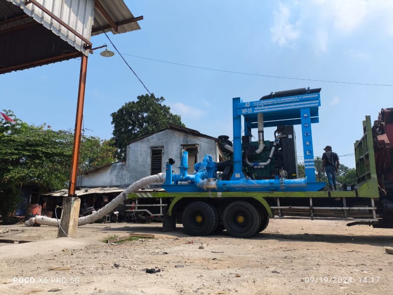
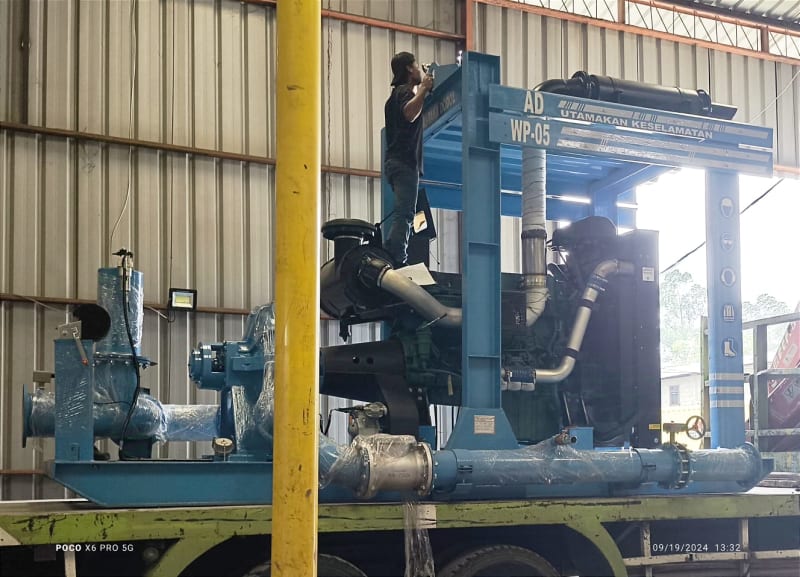
so right now im making dewatering pump using diesel engine as its motor and splitcase pump as the suction unit. we installed vaccum pump for it to be able to do self priming.

but it seems like the water wont fill the impeller room to full (we suspect the splitcase volute is filled with water, but doesn't fill up to full).

why is that?
 
Replies continue below

Recommended for you

Where is the connection for the vacuum pump?
what stops water getting into the vacuum system?

Got a drawing / sketch / picture?

What's the vertical lift from water level to pump centreline?

what sort of "vacuum" do you have? (mbara or similar pressure)

does it work anyway when you start the diesel engine?

Remember - More details = better answers
Also: If you get a response it's polite to respond to it.
 
WhatsApp_Image_2024-10-17_at_18.25.51_1e8aecfc_qpifjw.jpg

- the vacuum pump is located near the coupling area.
- it is connected to vacuum chamber on top of the suction pipe.
- the vacuum pump is working, water is filled up from the foot valve, suction pipe, and inside of the pump.. but the vacuum stops when the water only reached certain level inside the volute which is not enough to discharge the water. i dont know why that is.
- vertical lift to centre of impeller is probably 3-4 meters.

is it possible that splitcase pump cant use self priming system, due to the room inside the volute?

btw the pump works normally if we fill the volute with water using separate water pump, but that defeats the purpose of self priming system.
 
Ok, looking at that picture and your text, is the vaccuum line connected to the large blue tee? tot he left of the pump looking at the photo?

You really need to connect the line to the top vent of the pump casing.

Or lift the water in the main pipe the way you are now then when it fills, turn on a line to the vacuum pump from the top vent point of the pump casing.

But you also need to isolate the pump. Is the discharge valve isolated?

where does the wate go? I don't see any connecting pipe.

Can you get a closer up view of the pump?

Remember - More details = better answers
Also: If you get a response it's polite to respond to it.
 
WhatsApp_Image_2024-10-17_at_19.52.50_ff8d8b50_m9dqdl.jpg

this is the closest photo i have.

Ok, looking at that picture and your text, is the vaccuum line connected to the large blue tee? tot he left of the pump looking at the photo?
that is correct sir.

You really need to connect the line to the top vent of the pump casing.
we tried moving the vacuum line to the top vent of the casing, but the result was the same as the first test run.

But you also need to isolate the pump. Is the discharge valve isolated?
all potential leak of air was already handled, such as leak from flanges, foot valve, pump casing, butterfly valve, etc.

where does the wate go? I don't see any connecting pipe.
the photo u see above is before shipment when we tested the engine for the first time, so we didnt connect the discharge pipe to anything yet. the actual use is at mining site.


i forgot to mention that we already sent the unit to site, but not with self priming system. we use separate water pump to fill the pump casing with water.
but im just curious, about why vacuum didnt work on it. we have achieved self priming system but only on end suction pump, this is the first time we try vacuum pump with splitcase pump.
 
but what exactly was the test procedure?

Did you start the pump first then open the discharge valve?

How did you control flow on start up for the test?

Filling the casing by pulling water into the casing by vacuum should have worked. Was the suction pressure not enough to lift the water?


Remember - More details = better answers
Also: If you get a response it's polite to respond to it.
 
- we start the engine
- the vacuump pump detects that there is still air in the vacuum chamber (located at the front of the pump casing).
- vacuum sucks out air, and water starts filling in from foot valve.
- after water filled the vacuum chamber, the sensor trips and send signal to vacuum pump to stop working.

on end suction pumps, this means the water has filled the pump casing to maximum (because the height of vacuum chamber is higher than pump casing), and we can open the butterfly valve to let water discharge from outlet pipe.

but in this case, when the vacuum has stop working, we open the butterfly valve, there's nothing coming out, but the water is full on inlet pipe, and vacuum chamber.
we concluded that water indeed filled vacuum chamber to full, and reached pump casing, but somehow it stop filling the casing to full entirely.

Filling the casing by pulling water into the casing by vacuum should have worked. Was the suction pressure not enough to lift the water?
at first, we thought that our compressor is too weak, but after we switch it to bigger one, it still produced the same result.
 
Try just filling the pump casing from the top of the pump casing and THEN turning the engine on....

Or as I said first use the chamber and when that stops, connect the vacuum line to the top of the pump casing to fill the last little bit, then turn the pump on and crack open the butterfly valve just after the engine starts.

Remember - More details = better answers
Also: If you get a response it's polite to respond to it.
 
With a suction head of 3 meters there will be an absolute pressure of about 3 meters of water column absolute pressure in the pump chamber.
That is, about 2/3 of the mass of air in the pump chamber will be trapped when the lower piping floods.
You need a vacuum connection to the top of the pump chamber to remove this trapped air.
OP said:
we tried moving the vacuum line to the top vent of the casing, but the result was the same as the first test run.
The vacuum chamber is probably filling before all the air has been removed from the casing.
Possibly a small chamber above the pump casing to house the level sensor.
Alternately, a time delay to allow the pump to completely fill after the vacuum chamber has filled.
Intuitively, I would expect the vacuum chamber to fill completely while the air was still being drawn out of the pump casing.
Water will move in that large pipe and chamber much faster than air will move in a small vent line.
Two things are needed:
1. A vent line to the top of the pump casing.
2. Enough time must be allowed for the air to be completely removed from the pump casing or the sensor must monitor the pump casing rather than the vacuum chamber.

--------------------
Ohm's law
Not just a good idea;
It's the LAW!
 
Back
Top